PCB circuit board bonding process explanation
PCB circuit board bonding (bonding) is a wire bonding method in the chip production process. It is generally used to connect the internal circuit of the chip with gold or aluminum wires to the package pins or the gold-plated copper foil of the bonding circuit board before packaging. The ultrasonic wave of the ultrasonic generator (generally 40-140KHz) produces high-frequency vibration through the transducer, and transmits it to the wedge through the horn. When the wedge is in contact with the lead wire and the welded part, it will be under the action of pressure and vibration., The surface of the metal to be welded rubs against each other, the oxide film is destroyed, and plastic deformation occurs, causing the two pure metal surfaces to come into close contact, achieving a combination of atomic distance, and finally forming a strong mechanical connection. Generally, after bonding (that is, after the circuit and the pins are connected), the chip is packaged with black glue.

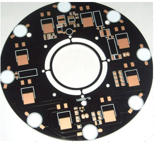
Process flow: clean PCB circuit board-drip bonding glue-chip paste-bond wire-sealing glue-test
1. Clean the PCB circuit board
Use the skin to wipe the oil, dust, and oxide layer on the position, and then clean the wiping position with a brush or blow it off with an air gun.
2. Dripping adhesive glue
The amount of glue drops is moderate, the number of glue dots is 4, and the four corners are evenly distributed; the bonding glue is strictly forbidden to contaminate the pad.
3. Chip paste (bonding)
Using a vacuum suction pen, the suction nozzle must be flat to avoid scratching the surface of the wafer. Check the direction of the chip. When sticking to the PCB circuit board, it must be "smooth and straight": flat, the chip is parallel to the PCB and there is no vacant position; stable, the chip and the PCB circuit board are not easy to fall off during the whole process; positive, the chip and the PCB The reserved position is pasted upright and cannot be deflected. Pay attention that the direction of the chip must not be pasted upside down.
4. State line
Bonding PCB boards have passed the bonding tensile test: 1.0 wire is greater than or equal to 3.5G, 1.25 wire is greater than or equal to 4.5G.
Standard aluminum wire with a fixed melting point: the wire tail is greater than or equal to 0.3 times the wire diameter, and less than or equal to 1.5 times the wire diameter. The shape of the aluminum wire solder joint is oval.
Solder joint length: greater than or equal to 1.5 times the wire diameter, and less than or equal to 5.0 times the wire diameter.
The width of the solder joint: greater than or equal to 1.2 times the wire diameter, and less than or equal to 3.0 times the wire diameter.
The bonding process should be handled with care, and the points must be accurate. The operator should observe the bonding process with a microscope to see if there are any defects such as broken bonding, winding, deviation, cold and hot welding, aluminum lifting, etc., if there is any To notify the relevant technical personnel to solve the problem in time.
Before the formal production, there must be a first-hand inspection to check whether there are any errors, few or missing states. In the production process, there must be a dedicated person to check its correctness at regular intervals (up to 2 hours).
5. Sealing glue
Before installing the plastic ring on the chip, check the regularity of the plastic ring to ensure that its center is square without obvious distortion. When installing, ensure that the bottom of the plastic ring is closely attached to the surface of the chip, and the photosensitive area in the center of the chip is not blocked. .
When dispensing, the black glue should completely cover the sun ring of the PCB board and the aluminum wire of the bonding chip. It cannot expose the wire. The black glue cannot seal the PCB sun ring. The leaked glue should be wiped off in time. The black glue cannot pass through the plastic ring. Penetrate into the wafer.
During the glue dispensing process, the needle tip or wool tag should not touch the surface of the chip in the plastic ring or the bonding wire.
The drying temperature is strictly controlled: the preheating temperature is 120 ± 5 degrees Celsius, and the time is 1.5-3.0 minutes; the drying temperature is 140 ± 5 degrees Celsius, and the time is 40-60 minutes.
The surface of the dried vinyl shall not have pores or uncured appearance, and the height of the vinyl shall not be higher than the plastic ring.
6. Test
Combination of multiple test methods:
A. Manual visual inspection;
B. Bonding machine automatic wire bonding quality inspection;
C. Automatic optical image analysis (AOI) X-ray analysis to check the quality of the inner solder joints.