The English full name of PCB proofing is PrintedCircuitBoard proofing.
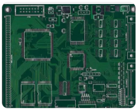
PCB proofing detailed introduction PCB's Chinese name is printed circuit board, also known as printed circuit board, printed circuit board is an important electronic component, the support of electronic components, and the provider of electrical connections for electronic components. Because it is made by electronic printing, it is called a "printed" circuit board.
PCB proofing refers to the trial production of printed circuit boards before mass production. The main application is the process of small batch trial production to the factory by electronic engineers after designing the circuit and completing the PCB Layout, which is PCB proofing. The production quantity of PCB proofing generally has no specific boundaries. Generally, engineers call it PCB proofing before the product design is confirmed and tested.
Circuit board welding process
1. PCB board welding process
1.1 PCB board welding process introduction
PCB board welding process requires manual plug-in, manual welding, repair and inspection.
1.2 PCB board welding process
Categorize components according to the list-plug-in-soldering-cutting feet-inspection-trimming
PCB board welding process requirements

2.1 Process requirements for component processing
2.1.1 Before inserting components, the solderability of the components must be processed. If the solderability is poor, the pins of the components must be tinned.
2.1.2 After the component pins are reshaped, the pitch of the pins shall be consistent with the pitch of the corresponding land holes on the PCB board.
2.1.3 The shape of the component lead processing should be conducive to the heat dissipation of the component during welding and the mechanical strength after welding.
2.2 Process requirements for inserting components on the PCB board
2.2.1 The order of inserting components on the PCB board is low first, then high, first small and then large, first light and then heavy, first easy and then difficult, first general components and then special components, and it cannot be affected after the previous process is installed. Installation of the next process.
2.2.2 After the components are inserted, their marks should be oriented in a direction that is easy to read and read as far as possible from left to right.
2.2.3 The polarity of the components with polarity should be installed in strict accordance with the requirements on the drawing, and the installation can not be wrong.
2.2.4 The insertion of components on the PCB board should be evenly distributed and arranged neatly and beautifully. Oblique, three-dimensional crossing and overlapping arrangements are not allowed; one side is not allowed to be high and the other is low; and the pins are not allowed to be long on one side and short on the other.
2.3 PCB board solder joint process requirements
2.3.1 The mechanical strength of the solder joints should be sufficient
2.3.2 Reliable welding, ensuring electrical conductivity
2.3.3 The surface of the solder joints should be smooth and clean
Electrostatic protection of PCB board welding process
3.1 Principle of electrostatic protection
3.1.1 Prevent static electricity from accumulating in places where static electricity may occur, and take measures to keep it within a safe range.
3.1.2 The existing static electricity accumulation should be quickly eliminated and released immediately.
3.2 Static electricity protection method
3.2.1 Leakage and grounding. Ground the parts that may or have generated static electricity to provide static discharge channels. Use the buried wire method to establish an "independent" ground wire.