With the development of new energy intelligent network technology, vehicle design is no longer the conventional 12V system, on the one hand 380V and other high voltage, on the other hand in the integrated circuit, 1.3V and other lower voltage. At the same time, LDO is no longer used in the power supply chip design process, and the use of Buck and Boost power supply increases. Therefore, EMC design of power supply is becoming more and more important. This paper takes a PCB board of a power supply as an example to analyze common problems in PCB board design of power supply, hoping to provide some ideas for you to solve EMC problems of power modules.

Design issues:
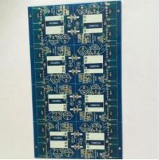
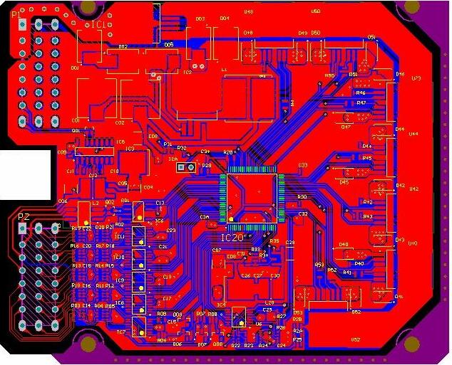
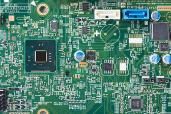
The PCB of the power board designed by a hardware engineer is shown in the figure below.
During THE EMC design review, a large number of EMC problems and hidden dangers were found on the board. Revision is required; otherwise, the board faces great EMC risks.
Problem one interface filter is too far from the interface
Problem two interface filter parts are not arranged vertically in a row
Problem three: the power filters are not arranged together
Problem 4 Switching power input and output loop is too large
Design idea:
Switching power supply board in PCB wiring control input rectifier filter loop, power loop, output rectifier loop, output filter loop loop loop area, loop should be small, wiring should be short!
Rectification design:
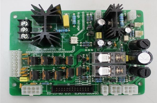
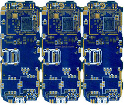
The redesigned PCB after optimization is shown below.
EMCLayout design essentials
Keep sensitive signals away from high current signals, especially frequency signals, and do not run parallel lines.
The current loop should be routed as small as possible.
Analog ground and power ground need to be separated, and can be connected through holes or star points.
Multi-channel IC power supply, can be connected to single point grounding, reduce crosstalk.
The control loop is separated from the power loop.
The decoupling capacitor needs to be placed near the IC power Pin.
Power supply multi-order filtering, small capacitance close to chip Pin.
The anti-reflection and clamp protection devices are placed close to the connectors.
Good isolation design of high pressure and low pressure ground
Pay attention to the spacing of safety cables