How to proceed to analyze defective PCBA electronic products and defective BGAs that have been repaired is just a common logical problem. However, many novice engineers do not know how to start when they receive defective PCBA products returned from customers or the market.
In fact, analyzing defective products is really like CSI or NSCI albums. You have to apply scientific methods to unravel the truth step by step. You must first collect (observe) evidence and determine the possible causes of crimes. It seems a little too invested in the album. It should be to assume various possible causes, and then verify step by step, and finally find out the truth. If possible, it is better to copy the truth.
To be honest, all the engineering problems are similar to the methods of [8D report] and [Problem Solving]. The key point is how to proceed step by step, which may seem boring, but step by step can often avoid some accidental leftovers. Details, you may even get some unexpected gains, the so-called devil is hidden in the details.
The following are some of the steps and experiences for analyzing defective PCBA products. Because they are sorted out based on their own memory and experience, there may be some missing or missing places. If there are friends who see deficiencies, please mention one or two:
1. If it is a machine that has not been disassembled, you can perform visual inspection and function test first to confirm that the product is really defective.
Sometimes the product returned by the customer is simply a good product and it is misjudged. The product itself may have no problem.

This may be caused by a problem with the customer's power supply or other problems, which has nothing to do with the product itself.
However, some product defects will only appear after being turned on for a period of time, and some will appear intermittently. At this time, the best way is to turn on the machine and let the automatic program run for at least one day, and do some basic operations to see if it is possible. The problem can be reproduced.
It is best to ask the customer under what circumstances the defect occurred before getting the defective product, so that you can grasp the situation and judge the possible cause of the defect.
In addition, it is recommended to check the appearance for any signs of impact falling from a height, because some undesirable reasons are damage to internal parts due to impact.
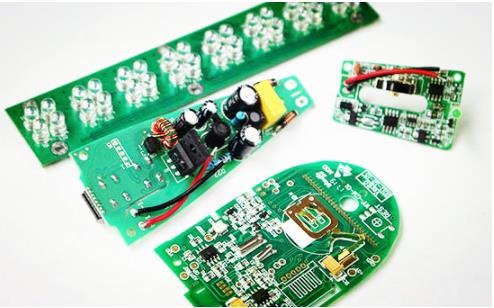
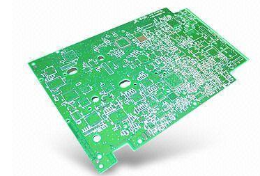
2. If the defective product obtained has been disassembled or only has a circuit board, it is recommended to do a visual inspection of the circuit board first.
Some repaired products may be caused by foreign objects (persons have seen cockroaches or spider webs in the machine, because the machine will be hot, humid and warm, very suitable for some insects to live), or accidentally contaminated liquid (the most We often see short circuit problems caused by beverages such as cola and coffee. In addition, some defective products can cause short circuits and burn parts or circuits due to some reasons. These can be roughly seen from the appearance.
It is recommended that you have used a microscope to check the condition of the circuits and parts on the circuit board, and do a carpet inspection, and do not let go of any clues.
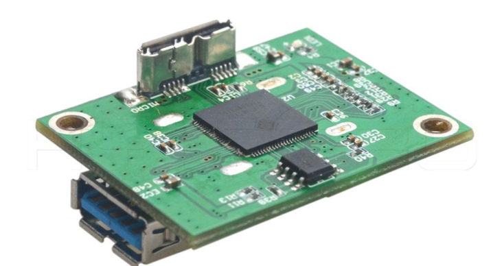
3. After checking the appearance of the PCB circuit board, do an electrical test again and measure the CPU temperature.
If the customer only returns the circuit board, it is necessary to perform the function test on the circuit board after the appearance inspection. The reason is the same as the first point. But even if the customer returns the whole machine, they can also do electrical tests on individual circuit boards to determine which circuit board is faulty, because some machines may consist of several boards, which can be preliminarily ruled out.
In addition, for those circuit boards that do not appear defective until a period of time after being turned on, you can try to measure whether the temperature of the main components (such as CPU) is normal. If the temperature rises abnormally, it indicates that there is a problem in the circuit. In fact, if the temperature is not The increase can also be used to determine whether the CPU is active or not.
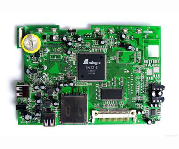
4. Perform circuit signal measurement, and confirm the defective parts and locations.
When we are unable to judge the cause of the bad from the appearance and basic electrical tests, we must start to do a more in-depth analysis. At this time, we can usually see the electronic engineer holding the electric meter and the oscilloscope there and poke right there, check Which line is not conductive or short-lived, or the voltage is wrong, or there is a problem with the timing of the IC parts. In short, it is necessary to find out which points of that part may be faulty.
5. After the circuit measurement, it is judged that there is a problem with the BGA.
It is best to know whether the BGA is a short circuit or an open circuit, and also to point out the possible solder joint positions. I believe that the electronic engineer has this ability.
5.1 If it is a BGA short circuit
Just take a photo of X-Ray and you can probably know what happened, but if it is a defective product returned by the market, the probability should not be high, because the basic electrical test has been done and passed before leaving the factory.
There are some short-circuit problems, even if you look at X-Ray, you can definitely see the problem. At this time, you may need to check if it is caused by flux and moisture, but such causes usually only occur. It appears during the environmental test. Generally, the real customers return because there are not many problems caused by the flux, but it can't be ruled out, especially for the relatively fine-pitch BGA.
5.2 If the BGA is open, there are several possibilities:
5.2.1 The bonding wire in the IC package is broken or the bonding wedge is off, but it can be judged by using X-Ray.
5.2.2 The solder joints of the BGA solder balls are open. First know which solder ball has the problem, and then use X-Ray to check it. It's just that the solder joints that are generally empty or broken are difficult to see with X-Ray. If the problem is the solder balls on the periphery of the BGA, you can consider using optical methods such as a microscope or a snake tube to check. If there are no other parts to block, you can generally see the two outermost rows of BGA solder balls directly, and it is most likely to happen. Most of the Pillow Correction (HIP) area is also located near the solder balls on the periphery of the BGA. This is because the circuit board and the BGA carrier board are prone to board bending during reflow soldering.
5.2.3 If none of the above methods can find the answer, finally consider using the red ink test (Red Dye Penetration) and the method of slicing.
It must be emphasized that these two methods are best to entrust experienced personnel to make analysis, because both of these are permanent damage tests, so they should be arranged until the last step.
If you only have one piece of defective product, I personally suggest to slice it directly, because the slice is finer, you can see the problem more, and there is a chance to see the problem of the BGA solder joints and the PCB structure at the same time, because the open circuit does not only occur in the BGA Solder joints may also appear in the sockets stacked inside the PCB. When making slices, you must cut off the problematic PCBA for analysis, so you must specify exactly which BGA has the problem, and it is best to point out the solder joint of the BGA. This saves time because it is made. Slicing is very time-consuming. If you look at the BGA solder balls in a row, although you can see the problem, you always think it’s easy to make mistakes, because you have to observe dozens or even hundreds of solder balls at a time., There is always time to show flowers after watching too much.
If you have several pieces of circuit boards with the same defects that can be analyzed, then consider the red ink test, because red ink is a relatively rough destruction analysis method, and you can only see if the solder joints have cracks and defects such as HIP. And judgment is also a science, but if it is a large area of poor solder joints, red ink can be an effective method, because you can see all the solder joints of the entire BGA at one time.