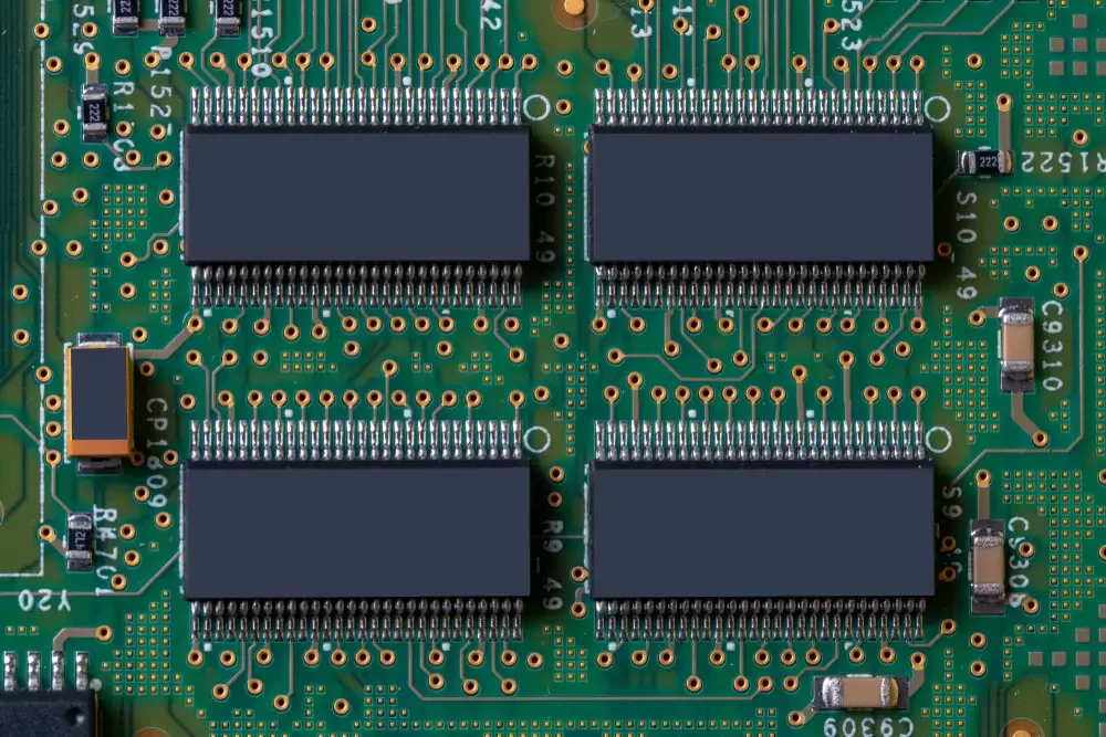
Metal core PCB are composed of a highly thermally conductive dielectric layer, metal layer, and a copper film with high heat dissipation capabilities. The most commonly used manufacturing materials are aluminum and copper, sometimes stainless steel is also used. Metal or aluminum PCBs can dissipate heat from high-power components to facilitate heat transfer. Therefore, the purpose of using this PCB is to provide much higher thermal conductivity compared to FR-4.
Advantages of metal core PCB:
In many aspects, LEDs are just like any other component installed on a circuit board. If only a few LEDs are present, such as green and red indicator lights for power on and off, there's nothing exceptional in arranging the PCB. However, there are lighting solutions that can keep LEDs or long arrays of LEDs on for long periods. Keeping these devices cool to prevent premature failure or safety hazards can be a major concern. Efficient cooling also requires ensuring consistent light output. Transitioning your PCB from standard FR4 types to MCPCB like aluminum PCBs is a worthwhile option. It uses specially formulated substrates to enhance the reliability of designs operating at tem
peratures above normal. The substrate is not strictly used as mounting surfaces for various components but actively absorbs heat from heat-running components to efficiently and safely dissipate heat into the relative layer of the circuit board. MCPCBs have proven to be an excellent solution for cooling PCBs with a large number of LEDs. Understanding the differences between standard epoxy glass boards and them is crucial.
Applications of metal core PCB:
LED Lighting: MCPCBs are usually suitable for applications that generate a significant amount of heat, where traditional fans cannot eliminate the heat efficiently. We often find MCPCBs in LED technology because they enable us to reduce the number of LEDs required for a certain amount of illumination and decrease the heat generated.
Automotive: Automotive power regulators, ignition, switch converters, variable optics, etc., all use metal PCBs. Power Equipment: Power converters, switching regulators, high-density power conversion.
Military and Aerospace: PCBs in military and aerospace applications must withstand extreme temperatures, thermal cycling, and moisture. Additionally, they must endure frequent mechanical shocks. Therefore, we use MCPCBs as they meet these service requirements and allow for higher structural integrity. Their high thermal conductivity ensures uniform temperature distribution on these boards. Thus, they can better withstand thermal cycling, preventing hotspots from forming near active components.

Metal core PCB
Comparison between metal core PCB and Standard PCBs:
Thermal Conductivity: Standard PCBs have a low thermal conductivity coefficient, typically around 0.3W, while MCPCBs have higher thermal conductivity, ranging from 1-2W.
Plated Through-Holes: Plated through-holes are often necessary in standard PCBs, but they may not be required in MCPCBs.
Heat Dissipation: Heat dissipation in standard PCBs often requires through-holes, leading to longer drilling cycles and additional processes. However, MCPCBs do not need drilling, plating, or deposition processes, as the metal core allows for effective heat dissipation.
Solder Mask: The solder mask layers in standard PCBs are usually dark-colored, such as black, green, blue, and red. Therefore, solder mask layers are applied on both the top and bottom in standard PCBs. In contrast, in MCPCBs, only the top is coated with a solder mask, which is typically white.
Thickness: Standard PCBs have a wide range of thicknesses due to layer stacking and various material combinations. However, the thickness variation in MCPCBs is usually limited due to available dielectric thicknesses and backing plate thicknesses.
Manufacturing Processes: Standard PCBs use traditional manufacturing processes such as routing, plated through-holes, drilling, and V-scoring. However, a diamond-coated saw blade is required to V-score MCPCBs because cutting metal requires sharp tools.
Things to consider for PCB manufacturers:
There are some handling considerations for MCPCB manufacturing, but as long as you understand how the material works and keep the design to a single-layer SMT type, designing your board shouldn't be much different than designing any other single-chip board , multi-layer PCB. If you find that you are unable to route your design to a single layer, please note that other MCPCB configurations are possible, although they are outside the scope of this article. These include:
2 layer PTH board with aluminum inside (this requires expensive pre-drilling/filling insulation/re-drilling steps to create plated through holes that won't short out).
A2 or more layer board manufactured according to standard PCB processes, but using thermal dielectric material instead of FR4 and laminating a metal backplane to the bottom for heat transfer.
When the design prioritizes cooling of multiple LEDs, MCPCB can be an excellent solution. They are becoming increasingly common in a variety of lighting applications - for homes, workplaces and vehicles. Although they are subject to certain design constraints, the manufacturing process is different from most other PCBs and is somewhat simpler.
Above is an introduction to metal core PCB.