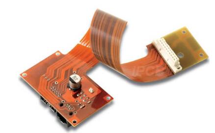
Flexible PCBs are designed for bending, and the bending radius is a key factor in ensuring the functionality and durability of the circuit board. The bending radius of a flexible PCB is the range or degree to which a circuit board can be safely bent.

This mainly depends on the thickness and stiffness of the material used, as well as the number of layers and the position of any rigid area. The design guidelines for the bending radius of flexible PCBs are:
1) Avoid using sharp turns (90 degrees) and instead use gradient curves
2) The use of PCB cutouts also helps to reduce the bending radius
3) Also reduce the thickness of copper wiring, so that the circuit board can bend better
When FPC flexible PCBs are bent, the types of stresses on both sides of the centerline are different. The inner side of the curved surface is pressure, and the outer side is tension. The magnitude of the stress applied is related to the thickness and bending radius of the FPC flexible circuit board. Excessive stress can cause delamination of FPC flexible circuit boards, copper foil breakage, and so on. Therefore, the lamination structure of FPC flexible PCBs should be reasonably arranged during design, so that the lamination at both ends of the bending surface centerline is as symmetrical as possible. At the same time, the minimum bending radius should be calculated based on different application scenarios.
Factors affecting the calculation of the bending radius of Flex PCB
1) Thickness of substrate
Thicker substrates often have larger bending radius because of their poor flexibility. On the other hand, thinner substrates are more prone to bending, thus having a smaller bending radius. Select the appropriate substrate thickness according to the specific requirements of the design of the Flex PCB to ensure optimal flexibility and reliability.
2) Number and type of copper layers
The copper layer provides electrical connections, which helps improve the overall rigidity of the board. If there is a copper layer in the soft board, the bending radius needs to be larger to prevent damage to the copper wiring or through holes during the bending process. In addition, the type of copper used, such as standard copper or high-temperature copper, can also affect the bending radius of the flex PCB.
3) Flexibility of covering materials
The flexibility of the covering material is another factor that affects the bending radius. The covering material is a protective layer used in flexible circuits to protect copper and provide insulation. The flexibility of the covering material can vary depending on its composition and thickness. More flexible covering materials allow for smaller bending radii, while less flexible covering materials require larger bending radius to avoid cracking or delamination.
4) Overall design (placement of components and wiring)
Components near the bending area may require a larger bending radius to prevent any interference or damage. Therefore, it is necessary to carefully plan the wiring to avoid sharp corners or sharp bends, as they may lead to stress concentration points and failure during the bending process.
Method for calculating the bending radius of flex PCB
1) A common method is to use the IPC-223 standard, which provides guidelines for calculating bending radius based on the thickness and number of layers of soft and hard boards. This standard takes into account the material properties and the mechanical stress that soft and hard boards bear during the bending process.
2) Another method is to use the formula to calculate R=T × K. Where R is the bending radius, T is the PCB thickness, and K is a constant value that depends on the material properties. This formula provides a general estimate of the bending radius and can serve as a starting point for further analysis and optimization.
The flexible layer continues to serve as an inner layer within the rigid part and can be used for conductor wiring. The flex PCB minimum bending radius is usually between 1mm and 6mm. Only by using single-layer and double-layer flexible PCBs can dynamic bending stress be reliably guaranteed.