In order to find the faults of PCB manufacturing as soon as possible, this article analyzes the common causes of PCB faults, combined with circuit knowledge, and summarizes a set of very operational PCB fault detection procedures and four "sequential" principles in long-term practice. Finally, from the perspective of the development of detection means and detection technology, the development trend of PCB fault detection is summarized.
1 PCB and analysis of common failure factors
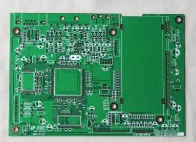
1.1 PCB overview
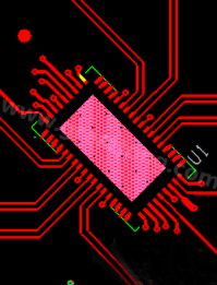
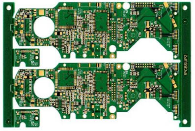
PCB is the abbreviation of printed circuit board. It is to etch the connections between various components in electronic equipment to the copper clad board in advance through a series of processes. The consistency of the electronic components, thereby avoiding manual wiring errors, and realizing automatic insertion or placement of electronic components, automatic soldering, automatic detection, ensuring the quality of electronic equipment, improving labor productivity, reducing costs, and facilitating maintenance .
1.2 Analysis of common failure factors of PCB
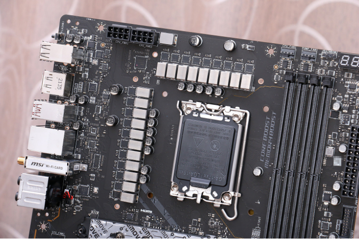
With the complexity of the circuit and the integration of components, it is inevitable that various failures will occur in the production and use of the circuit board. Through long-term practice, this article has concluded that the circuit board failure mainly has the following factors:
1) The layout of the circuit board is not reasonable enough, and it is disturbed by wiring and surrounding components electromagnetically;
2) The circuit board components are damaged, causing the system to fail to work normally;

3) The performance of the components is unstable due to its own reasons, resulting in unstable operation of the equipment;
4) There is no damage to the components of the electronic equipment, and the cause of the inability to work is caused by the solder joints and other reasons, which will cause the circuit to open or short
2 The general process and principles of PCB fault detection
2.1 What should be done before PCB fault detection
1) Understand the working environment of the equipment, mainly considering the possible impact of external electrical parameters on the equipment;
2) Ask what happens when the circuit board fails, and analyze the cause of the failure;
3) Check the components on the circuit board carefully to find out which components play a key role on the circuit board;
4) Take measures to prevent electromagnetic interference and static electricity.
2.2 The general process and principles of PCB fault detection
2.2.1 From manual observation to instrument measurement, that is, "look first and then measure"
The components in electronic equipment and the wires between them are almost all distributed on the surface of the circuit board. When a circuit board fails, you should first observe it with the naked eye. If you want to get better results, use a microscope, magnifying glass and other optics. The instrument can help us find the problem more accurately, no matter what method is used, we should focus on finding out whether there are the following situations:
1) Whether the connection between PCB components is complete, whether the power supply, ground and other special points are working properly;
2) Whether the pins of integrated chips, diodes, triodes, resistors, electrolytic capacitors, inductors and other components have fewer or random connections;
3) Whether there are operational problems in the solder joints of each component, such as virtual soldering, missing soldering, and wrong pin insertion;
2.2.2 From the periphery to the inner layer, that is, "first outside and then inside"
According to the previous analysis, the circuit board failures caused by components account for the largest proportion, so how to find the problem components more efficiently is very important.
2.2.3 From simple to complex, that is, "Easy first and complicated later"
In the process of PCB fault detection, it is necessary to adopt some test techniques, and the use of these test techniques should follow the principle of "Easy first and complicated later".
1) What should be done before PCB testing
Circuit board simulation is a very effective way to design circuit boards, which can greatly reduce the design cycle and cost, but simulation is the result of the ideal conditions of each component, ignoring various interferences in actual work. Therefore, shielding all kinds of interference before the test has a great influence on the test effect. The general shielding methods are: short-circuit the crystal oscillator. In addition, because the charging and discharging of the capacitor can also cause interference, solder a pin to the large electrolytic capacitor to make it work in an open circuit state. In order to avoid the impact of the test on the CPU, the CPU should be Remove.
2) "Easy first and complicated later" in the use of specific detection methods
The inspection of components often starts with simple components and gradually detects more complex components. This is because the simpler the component, the easier it is to find its problems. In the process of testing the device, use the exclusion method, that is, "test one pass and one" and make a record; if the test fails, in order to ensure the accuracy, you can test again, if it still fails, you can record the result first, and then Measure the next one until the components on the circuit board are tested. For those components that fail the test, they can be regarded as key suspects.
3) Supplements between different test methods
In practice, if you only use one method for testing, you may still not find the fault. The simpler method is to start with a simple test method. The simple method can find the fault without the complicated method. Of course, the simple method is used in some cases. If it is not easy to find the problem, then a more advanced method should be chosen as a supplement. PCB testing methods have gone through manual visual inspection (MVI), online testing (ICT), and then boundary scanning technology (BST), and now non-vector testing technology has been added.
2.2.4 From static detection to dynamic detection, that is, "static first and then moving"
One method is to measure the voltage of the pins. For different pins, the voltage value of the circuit board should be different when the circuit board is normally powered. However, when using this method, various influences should be considered. For example, the pins are not sensitive and adjacent Whether the component is faulty, etc. Another method is to measure the resistance online. Because the IC uses direct coupling, the DC resistance between the other pins of the IC and the ground pin is relatively fixed. This equivalent resistance is called the internal DC resistance of the pin, or R for short. Inside. Therefore, the internal DC resistance of each pin can be measured by a multimeter to determine the status of each pin. If the measured R of each pin is consistent with the reference value, it can be determined that the integrated circuit is working normally. On the contrary, if it is different from the reference value. If it is large, it indicates that there is a problem inside the integrated chip and should be replaced. In testing, online voltage and online resistance measurement methods are often used in combination.
3 concluding remarks
At present, PCB testing technologies that combine multiple disciplines are becoming more and more diversified. Each testing technology has its own scope of application. For example, the online testing method is limited by the device test library, and the boundary scan method has strict requirements for reference circuit boards. Require. Therefore, in practice, in order to make PCB fault detection more accurate and efficient, taking the general process proposed in this article as a reference and following the four detection principles, flexible use of various detection techniques will make PCB fault detection more automated, intelligent and efficient. change.