In order to better learn about operational amplifiers, the following 16 questions and answers can quickly familiarize yourself with the basics of operational amplifiers.
1. In general, there will be a balance resistance in the inverting / in-phase amplifier circuit. What is the function of this balance resistance?
(1) Provide a suitable static bias for the transistors inside the chip.
The circuits inside the chip are usually directly coupled, which can automatically adjust the static working point. However, if an input pin is directly connected to the power supply or ground, its automatic adjustment function is abnormal, because the transistors inside the chip can not raise the voltage of the ground wire or pull down the voltage of the power supply, which leads to the chip can not meet the conditions of virtual short and virtual break, The circuit needs to be analyzed separately.
(2) To eliminate the influence of static base current on the output voltage, the magnitude should be balanced with the equivalent resistance of the external DC path at the two input terminals, which is also the reason for its name.
2. What is the function of in-phase proportional operational amplifier with a capacitor on the feedback resistance[/ H1] (1) feedback resistor and capacitor form a high pass filter, which is particularly powerful for local high-frequency amplification.
(2) Prevent self excitation.

Basic understanding of operational amplifier
3. What are the consequences if the in-phase amplifier circuit of the operational amplifier is not connected to the balance resistance?
Burning the operational amplifier may damage the operational amplifier, and the resistance can play the role of voltage division.
4. What role can the pull-down resistor play in pulling up the capacitor at the input of the operational amplifier?
It is to obtain the problem of positive feedback and negative feedback, which depends on the specific connection. For example, if I take the current input voltage signal and output voltage signal, and then take out a wire at the output end to connect it to the input section, then due to the resistance above, part of the output signal obtains a voltage value after passing through the resistance, shunting the input voltage to reduce the input voltage, which is a negative feedback. Because the signal output by the signal source is always constant, the output signal can be corrected by negative feedback.
5. The operational amplifier is connected into an integrator. What is the role of parallel resistance RF at both ends of the integrating capacitor?
The discharge resistor is used to prevent the output voltage from getting out of control.
6. Why are resistors and capacitors usually connected in series at the input of operational amplifiers?
If you are familiar with the internal circuit of operational amplifier, you will know that no matter what operational amplifier is composed of several transistors or MOS tubes. In the absence of external components, the operational amplifier is a comparator. When the voltage at the in-phase terminal is high, it will output a level similar to the positive voltage, and vice versa... But this operational amplifier seems to be of little use. Only when an external circuit is formed in the form of feedback, can the operational amplifier have the functions of amplification, inversion and so on
7. What are the consequences if the balance resistance of the in-phase amplification circuit of the operational amplifier is wrong?
(1) The in-phase inverting terminal is unbalanced, and there will also be output when the input is 0. When the input signal is input, the output value is always a fixed number larger (or smaller) than the theoretical output value.
(2) The error caused by the input bias current cannot be eliminated.
8. What is the amplification factor of an ideal integrated operational amplifier, what is the input impedance, and what is the voltage between the in-phase input and the inverting input?
The magnification is infinity, the input impedance is infinitesimal, and the voltage between the same direction input and the reverse input is almost the same (not 0!!! (10V at the opposite end and 9.99999v at the opposite end)
9. Excuse me, why is the open-loop gain of an ideal operational amplifier infinite?
(1) The actual open-loop gain of the operational amplifier is more than 100000, which is very, very large. Therefore, the open-loop gain of the actual operational amplifier is imagined as infinity, and the virtual ground is derived.
(2) The derived virtual ground is only for the inverting amplifier.
It is seen in the book that the open-loop gain of the operational amplifier is infinite, so that when we design the circuit, the closed-loop gain can not be limited by the open-loop gain, but only depends on the external components. It is to sacrifice large open-loop gain for the stability of closed-loop gain.
(3) It is derived that the virtual ground is not only the inverting amplifier when the operational amplifier is connected with negative feedback; There is no virtual ground in positive feedback.
(4) It is well understood that if the gain is small, for an output voltage, the difference between the voltages applied at both ends of the operational amplifier is relatively large. If it is connected to the negative feedback state, the voltage at both ends of the operational amplifier will be inconsistent, resulting in amplification error.
(5) There are two conditions for the realization of "virtual short" of operational amplifier:
1) the open-loop gain a of the operational amplifier should be large enough;
2) there shall be negative feedback circuit.
First, we know that the output voltage Vo of the operational amplifier is equal to the difference vid between the positive phase input voltage and the reverse phase input voltage multiplied by the open-loop gain a of the operational amplifier. That is, VO = vid * a = (VI - VI -) * a (1) since the output voltage of the operational amplifier will not exceed the power supply voltage in practice, it is a limited value.
In this case, if a is large, (VI - VI -) must be small; If (VI - VI -) is small to a certain extent, we can actually regard it as 0. At this time, there will be VI = VI -, that is, the voltage at the in-phase input of the operational amplifier is equal to the voltage at the inverting input, which seems to be connected together. This is called "virtual short circuit". Note that they are not really connected, and there is resistance between them, which must be kept in mind.
In the above discussion, how do we get the result of "virtual short"?
Our starting point is formula (1), which is the characteristic of operational amplifier. There is no problem. We can rest assured. Then, we made two important assumptions. One is that the output voltage of the operational amplifier is limited, which is no problem. Of course, the output of the operational amplifier will not exceed the power supply, so this assumption is true, so we won't mention it in the future. The second is that the open-loop gain a of the operational amplifier is very large.
The a of an ordinary operational amplifier is usually up to the 6th, 7th power of 10 or even higher. This assumption is generally no problem, but don't forget that the actual open-loop gain of the operational amplifier is also related to its working state. If you leave the linear region, a is not necessarily large. Therefore, this second assumption is conditional. Let's remember this first.
Therefore, we know that when the open-loop gain a of the operational amplifier is large, the operational amplifier can have "virtual short". But this is only a possibility, not automatic. No one will believe that the two inputs of an operational amplifier are "virtual short"“ "Virtual short" can only be realized in a specific circuit.
The conditions for the existence of "virtual short" are:
1) the open-loop gain a of the operational amplifier should be large enough;
2) there shall be negative feedback circuit.
After understanding the conditions of "virtual short", we can easily judge when we can and can't use "virtual short" for circuit analysis. In fact, condition (1) is true for most operational amplifiers, and the key depends on the working area.
If it is the circuit in the book, judge by calculation; If it is an actual circuit, you can know whether the output voltage of the operational amplifier is reasonable by measuring the instrument. Another situation related to "virtual short" is called "virtual ground", that is, the "virtual short" when an input terminal is grounded, which is not a new situation.
Some books say that "virtual short" can only be used under the condition of deep negative feedback. I don't think this is accurate. I think the underlying thinking is that in the case of deep negative feedback, the op amp is more likely to work in the linear region. But this is not true. When the input signal is too large, the op amp with deep negative feedback still enters saturation.
Therefore, it should be judged reliably by the output voltage value.
10. The input signal is directly added to the in-phase input terminal, and the inverting input terminal is grounded through resistance. Why u_= U =Ui≠0? Isn't it an empty place?
Problem supplement: certain conditions must be met to form deficiency and shortness. Does it have to meet certain conditions to form a virtual land? What is it? Why?
(1) In the in-phase amplifier circuit, the output makes u () automatically track U (-) through feedback, so that u () - U (-) will be close to 0. It seems that both ends are short circuited, so it is called "virtual short".
(2) Due to the virtual short phenomenon and the high input resistance of the operational amplifier, the current flowing through the two input terminals of the operational amplifier is very small, close to 0. This phenomenon is called "virtual break" (virtual break is derived from virtual short, do not think the two are contradictory)
(3) The virtual ground is in the inverting operational amplifier circuit, () terminal is grounded, (-) input and feedback network. Due to the existence of virtual short, u (-) and U () [potential equal to 0] are very close, so it is called false grounding at (-) end - "virtual ground"
(4) About conditions: virtual short is an important feature of the closed-loop (in short, with feedback) working state of the in-phase amplifier circuit, and virtual ground is an important feature of the inverse amplifier circuit in the closed-loop working state. Pay attention to understanding the condition of virtual short (such as "close to equality"), it should be OK.
11. I always think there is something strange about the model of operational amplifier. The first is "virtual short", because "virtual short". When the operational amplifier is connected to the in-phase amplifier, the potentials of the two inputs are the same. At this time, if the waveform of the measured input is the same, it is like a common mode signal. In fact, there are still small differential mode signals on the two inputs, However, in this way, the "virtual short" artificially (because the virtual short is the result of deep negative feedback, which is artificial) increases the common mode signal at the two inputs, which poses a challenge to the performance of the operational amplifier. Why should operational amplifiers be used like this?
(1) The common mode signal of in-phase amplifier is much larger than that of inverting amplifier, and the requirement of common mode rejection ratio is high.
(2) My opinion on "common mode signal suppression ability of the same and inverse amplifiers" the advantages and disadvantages (DB value) of the common mode signal suppression ratio of the operational amplifier mainly depend on the symmetry and gain of the internal (only internal) differential amplifier of the operational amplifier. It is obvious that no operational amplifier provides its common mode rejection ratio and attaches the structural conditions of external circuits.
For single ended input, whether in-phase or inverse, the equivalent common mode value is half of the input value. However, because the input impedance of in-phase amplification is usually greater than that of inverse amplification, its anti-interference ability is certainly worse.
As mentioned above, when inverting input, the inverting terminal voltage is almost zero, so there is only one tube change in the collector voltage of the differential tube. During in-phase input, the voltage at the inverting end is equal to that at the in-phase end, so the common mode voltage is equal to the input voltage! That is to say, the collector voltage of the differential pair transistor changes in the same direction in addition to the parts of the two transistors that change in different directions at the same time, which is the common mode output voltage.
It is added in phase with the voltage of one of the tubes. Therefore, it is easy to lead to the saturation (or cut-off) of the tube. Fortunately, the amplification of the common mode voltage is only one tens of thousands of the differential mode magnification.
The above does not mean that the common mode rejection ratio of differential mode input and common mode input of the amplifier is different! It should be in-phase input, and a common mode signal equivalent to the input will be added! Therefore, the in-phase amplification mode should be used with caution when the input signal is large.
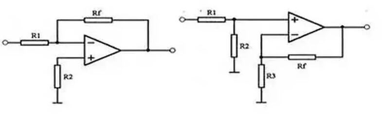
12. Why do op amps generally have to be inversely scaled?
The major difference between the inverse input method and the in-phase input method is:
For the inverting input method, a balance resistor is connected to the ground at the in-phase terminal, and there is no current on this resistor (because the input resistance of the operational amplifier is very large), so this in-phase terminal is approximately equal to the ground potential, which is called "virtual ground", and the electric potential of the inverting terminal and the in-phase terminal is very close, so there is also "virtual ground" at the inverting terminal.
The advantage of virtual ground is that there is no common mode input signal. Even if the common mode rejection ratio of this operational amplifier is not high, there is no common mode output. The in-phase input connection method has no "virtual ground". When a single ended input signal is used, a common mode input signal will be generated. Even if an operational amplifier with high common mode rejection ratio is used, there will still be a common mode output.
Therefore, in general, the inverse input connection method will be used as far as possible.
13. Some operational amplifiers will output even if no voltage is input after power on, and the output is not small, so VCC / 2 is often used as the reference voltage.
The operational amplifier has output without any input, which is caused by the asymmetric design structure of the operational amplifier itself, that is, the input offset voltage Vos, which is a very important performance parameter of the operational amplifier. VCC / 2 is often used as the reference voltage of the operational amplifier because the operational amplifier is in the working state of single power supply. At this time, the real reference of the operational amplifier is VCC / 2. Therefore, a DC bias of VCC / 2 is often provided at the positive end of the operational amplifier, and the ground is often used as the reference when the positive and negative power supplies are supplied.
Many matters need to be paid attention to in the selection of operational amplifier. Under not very strict conditions, the operating voltage, output current, power consumption, gain bandwidth product, price, etc. of operational amplifier often need to be considered. Of course, when the operational amplifier is used under special conditions, different influence factors need to be considered.
14. Why does the amplifier circuit composed of operational amplifier generally sample the inverse input mode?
(1) The major difference between the inverse input method and the in-phase input method is:
For the inverting input method, a balance resistor is connected to the ground at the in-phase terminal, and there is no current on this resistor (because the input resistance of the operational amplifier is very large), so this in-phase terminal is approximately equal to the ground potential, which is called "virtual ground", and the electric potential of the inverting terminal and the in-phase terminal is very close, so there is also "virtual ground" at the inverting terminal.
The advantage of virtual ground is that there is no common mode input signal. Even if the common mode rejection ratio of this operational amplifier is not high, there is no common mode output. The in-phase input connection method has no "virtual ground". When a single ended input signal is used, a common mode input signal will be generated. Even if an operational amplifier with high common mode rejection ratio is used, there will still be a common mode output. Therefore, in general, the inverse input connection method will be used as far as possible.
(2) The positive phase is the oscillator, the inverted phase can stabilize the amplifier, and the negative feedback is connected
(3) In principle, it is possible to connect in-phase proportional amplification circuit. However, in practical application, the amplified signal (i.e. differential mode signal) is often very small. At this time, attention should be paid to suppress noise (usually common mode signal). The in-phase proportional amplification circuit has poor suppression ability to the common mode signal, and the signal to be amplified will be submerged in the noise, which is not conducive to post-processing. Therefore, the inverse proportional amplification circuit with good suppression ability is generally selected.
15. What are the important features of the amplifier?
(1) If the voltage on both inputs of the operational amplifier is 0V, the output voltage should also be equal to 0V. But in fact, there is always some voltage at the output, which is called offset voltage Vos. If the offset voltage at the output is divided by the noise gain of the circuit, the result is called input offset voltage or input reference offset voltage. This feature is usually given in Vos in the data table.
The Vos is equivalent to a voltage source connected in series with the inverting input of the operational amplifier. A differential voltage must be applied to both inputs of the amplifier to produce a 0V output.
(2) The input impedance of the ideal operational amplifier is infinite, so there will be no current flowing into the input. However, a real operational amplifier using bipolar transistor (BJT) in the input stage requires some operating current, which is called bias current (IB). There are usually two bias currents: IB and IB -, which flow into the two inputs respectively. The range of IB value is very large, which is a special type of operational amplifier