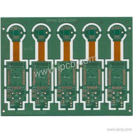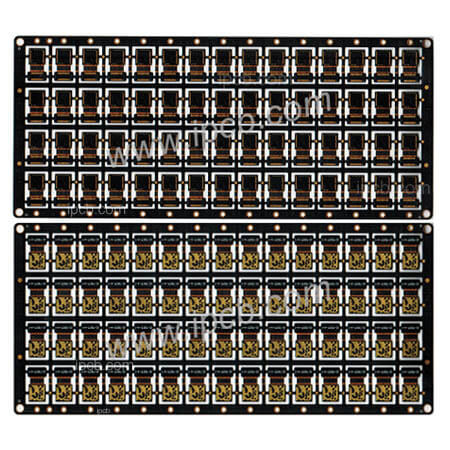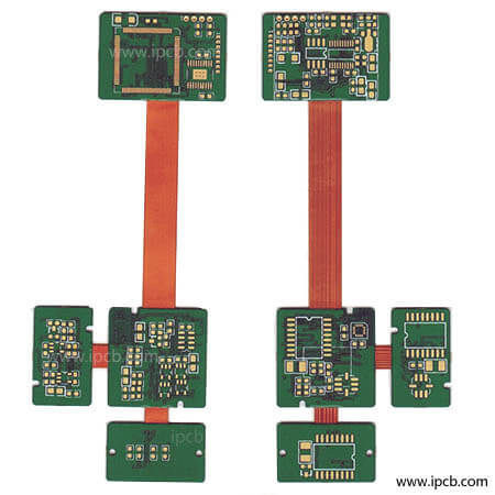
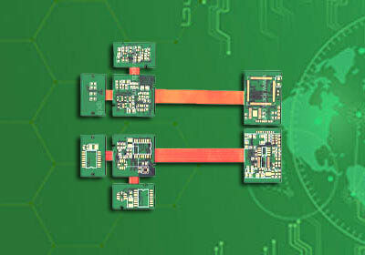

Model : 8Layers Rigid-Flex PCB(R-FPCB)
Material : FR4 + PI
Construction : FR4 4L+FLEX 4L
Finished Thickness : 0.2mm+0.8mm
Copper Thickness : 1OZ
Color : Green /White
Surface Treatment : Immersion Gold
Min Trace / Space : 5mil/5mil
Min Hole : Mechanical Hole0.2mm
Application : Equipment switching PCB
Rigid Flex PCB is derived from the development of FPC and PCB.Therefore, Rigid-Flex PCB is flexible PCB and rigid PCB. After pressing and other processes, they are combined according to relevant process requirements to form a PCB with FPC characteristics and PCB characteristics.
Because Rigid Flex PCB is a combination of FPC and PCB, the production of Rigid-Flex PCB should have both FPC production equipment and PCB fabrication equipment. First, the electronic engineer draws the circuit and shape of the flexible PCB board according to the needs, and then sends it to the factory that can produce Rigid-Flex PCB. The CAM engineer processes and plans the relevant documents, and then arranges the FPC production line production site FPC and PCB production lines are required to produce PCB. After these two FPC boards and PCB boards come out, according to the planning requirements of the electronic engineer, the FPC and PCB are seamlessly pressed by a pressing machine, and then a series of details are passed through. Became Rigid-Flex PCB. A very important link, because Rigid-Flex PCB is difficult and there are many details. It is generally inspected before shipment. Because of its high value, so as to avoid loss of related benefits to both the supplier and the demander.
What is a rigid Flex PCB?
The birth and development of FPC and PCB gave birth to the new product of rigid Flex PCB. Therefore, rigid Flex PCB is a circuit board with FPC characteristics and PCB characteristics formed by combining flexible circuit board and hard circuit board through pressing and other processes according to relevant process requirements.
Advantages of Rigid-Flex PCB
1. High impact and high vibration environment. Rigid-Flex PCB has high impact resistance, and can be applied in a high-stress environment and ensure stable equipment performance, otherwise it will cause equipment failure.
2. High-precision applications where reliability is more important than cost considerations. If cable or connector failure is dangerous, it is better to use the more durable Rigid-Flex PCB.
3. High-density applications. Some components lack all the necessary connectors and the required surface area for cables. In this case, Rigid-Flex PCB can be used to save space to solve this problem.
4. Applications that require multiple rigid PCB boards. When the assembly is packed with more than four connection boards, replacing them with a single Rigid-Flex PCB may be the best option and more cost-effective.

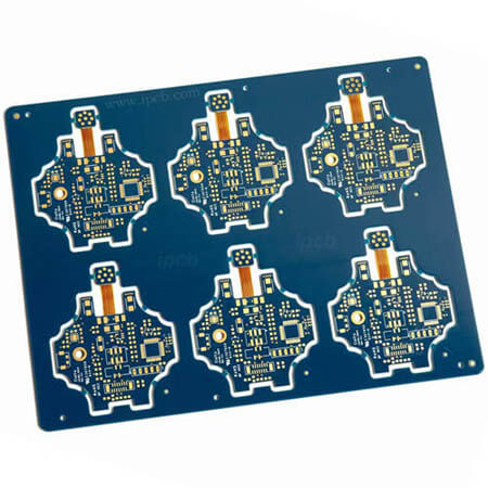
rigid flex pcb
Rigid flex PCB applications:
1. Industrial use-Industrial use includes Rigid-Flex PCB board used in industry and medical treatment. Most industrial parts require the characteristics of accuracy, safety, and resistance to soil damage. Therefore, the characteristics required for soft and hard boards are: high reliability, high precision, low impedance loss, complete signal transmission quality, and durability. But because the process is complicated, the cost is relatively high.
2. Cars-Rigid-Flex PCB board in cars are commonly used to connect the buttons on the steering wheel to the motherboard, the connection of the car's video system screen and the control panel, the operation connection of the audio or function keys on the side door, and the reversing radar. Image system, sensors (Sensor, including air quality, temperature and humidity, special gas adjustment, etc.), vehicle communication system, satellite navigation, rear seat control panel and front-end controller connection board, vehicle exterior detection system, etc.
3. Consumer electronic products-among consumer products, DSC and DV are representative of the development of R-F PCB board, and they can be discussed in two main axes: "performance" and "structure.
4. Mobile phone-the application of soft and hard boards in mobile phones, such as folding mobile phone turning point (Hinge), image module (Camera Module), keys (Keypad) and radio frequency module (RF Module), etc. are common. The advantages of using R-F PCB boards in mobile phones are the integration of parts in the mobile phone and the consideration of the amount of signal transmission.
Rigid flex PCB prototype laminate process
Even if the positioning holes are punched with OPE, the single-chip processing before lamination has a great influence on the alignment between layers.
We should pay attention to three aspects when handling the PCB board part:
1. Regardless of whether it is substrate pressing or pure prepreg pressing, it is important to note that the warp and weft directions of the glass cloth should be consistent, and the thermal stress should be eliminated during the pressing process to reduce warpage.
2. The PCB rigid board should have a certain thickness, because the flexible part of the PCB is very thin and has no glass cloth. After being affected by the environment and thermal shock, its changes are different from the rigid PCB part. If the rigid PCB part is not certain The difference in thickness or hardness will be obvious, and serious warpage will occur during use, which will affect welding and use. If the rigid part has a certain thickness or hardness, this difference may appear Insignificant, the overall flatness will not change with the change of the flexible part, which can ensure welding and use. If the rigid part is too thick, it will appear heavy and uneconomical. The experiment proves that the thickness of 0.8~1.0mm is more appropriate.
3. For the processing of flexible PCB windows, there are usually first milling and post milling methods to process, but it needs to be processed flexibly according to the structure and thickness of the Rigid-Flex PCB itself. If it is to mill the flexible window first The accuracy of the milling should be ensured, and neither the welding nor the deflection should be affected too much. The milling data can be produced by engineering, and the flexible window can be milled in advance. We don’t use milling and cutting of the flexible window first, and wait until we finish all the pre-processes and finally take shape and then use laser cutting to remove the waste of the flexible window. At this time, we must pay attention to the depth of the FR4 that the laser can cut.
rigid flex PCB manufacturing process 1 Material selection 2 Production process and control of key parts 2.1 Production process 2.2 Graphic transfer of the inner monolithic 2.3 Multi-layer positioning of flexible materials 2.4 Laminating 2.5 Drilling 2.6 De-drilling and protruding corrosion 2.7 Electroless copper plating, copper electroplating 2.8 Surface solder mask and solderability protective layer 2.9 Shape processing |
|
Rigid-flex PCB board is widely used, with the development of smart devices towards high integration, light weight, and miniaturization, as well as the new requirements of Industry 4.0 for personalized production. With its advantages and characteristics, the rigid-flex PCB board will definitely be able to show its talents in the future.
Rigid flex PCB design guidelines,flex rigid PCB design rules
1. The FPC layer of the Rigid-Flex PCB is designed to be as deep as possible on the same sheet and as intermediate as possible.
8-layer Rigid-Flex PCB, top/bottom make a single sheet, 2/3, 4/5, 6/7, each sheet uses priority 4/5 > 2/3=6/7 for FPC layer
10-tier Rigid-Flex PCB:T, 2/3, 4/5, 6/7, 8/9, B uses priority 4/5=6/7>2/3=8/9 for FPC layer
2. Due to the limitation of space or bending angle, the flexible PCB can be inserted into the board to meet the bending radius and space requirements. At this time, at least 1mm of soft and hard gaps should be met. The spacing between the branches of the hard and soft board is suggested to be greater than 0.8mm, flex vs rigid PCB and 2mm between the hard board and the hard board.
3. The length requirement of flexible PCB is related to bending angle and radius.
4. Consider the 3-D structure of the bent back panel to avoid interference between device installations (limit height)
5. The flexible PCB length of Rigid-Flex PCB is recommended to be greater than 5mm and the limit value is 4mm, otherwise some board factories may not be able to process it
Design-related
5. When the device is placed in the Rigid PCB region, the distance between the edge of the device and the Rigid-Flex region is greater than 1 mm.
6. Flexible PCB should not punch as much as possible. Hard zone drilling is recommended to be more than 2mm from the soft-hard junction
7. The Rigid-Flex junction should use arc transition as far as possible. The radius depends on the actual situation. 6.35mm is recommended but it is generally not. At least 0.5mm is recommended.
8. Rigid-Flex PCB flexible PCB part adjacent layer wiring uses staggered wiring, avoiding coincident wiring as much as possible, so that the flexe PCB softness can evenly increase bending life
9. The flexible PCB wiring should go straight in and out as far as possible. If the structure is limited to the soft-hard junction, the circular arc should also be used at the corner of the flexible PCB.
10. If cross-flexible PCB signals do not require impedance control, and copper (power-to-ground signal) is required on the flexible PCB part, grid copper is recommended
11. If the impedance is to be controlled across a flexible PCB signal it is important to note that the signal line still needs a reference plane in the flexible PCB, and that the impedance line width needs to be calculated separately is likely to change abruptly
12.Flexible PCB part keep devices as far as possible If installing devices build libraries, set the pad on the corresponding soft layer instead of top/bottom

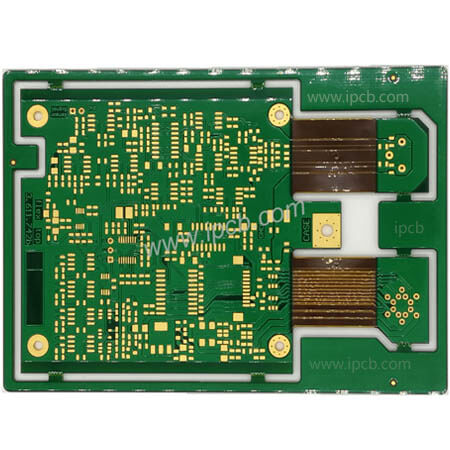
4 layer rigid flex PCB stackup
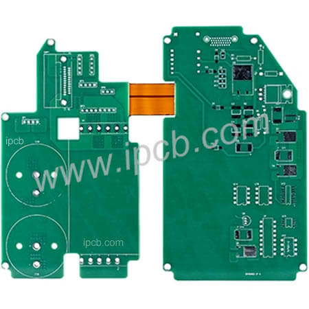
Rigid-flex PCB board adapter is a kind of transition product used for connection test with PCB. Its function is to use in various tests or change the existing structure. It can be widely used in LCD, car TV, industrial control medical equipment, etc.
Application of Rigid-flex PCB board adapter
It is widely used in LCD PCB, car TV PCB, industrial PCB, medical PCB, equipment PCB, computer PCB, communication PCB, automobile PCB, audio PCB, air conditioner PCB, refrigerator PCB and lighting PCB, digital camera and other electrical PCB appliances.
cost of rigid flex pcb
Due to the difference in the material between Flex PCB and Rigid PCB, mainly due to the difference in thermal expansion coefficient and adhesion between Flex PCB and rigid PCB, the cost of rigid flex PCB fabrication is much higher. So flex vs rigid PCB cost is very high. iPCB is a rigid Flex PCB supplier that provides the cheapest flex rigid PCB price. iPCB quickly replies to the rigid Flex PCB quote and provides one-stop service of rigid Flex PCB assembly. Manufacturing the best rigid flex PCB prototype is our goal.
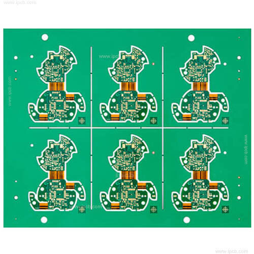
Model : 8Layers Rigid-Flex PCB(R-FPCB)
Material : FR4 + PI
Construction : FR4 4L+FLEX 4L
Finished Thickness : 0.2mm+0.8mm
Copper Thickness : 1OZ
Color : Green /White
Surface Treatment : Immersion Gold
Min Trace / Space : 5mil/5mil
Min Hole : Mechanical Hole0.2mm
Application : Equipment switching PCB
For PCB technical problems, iPCB knowledgeable support team is here to help you with every step. You can also request PCB quotation here. Please contact E-mail sales@ipcb.com
We will respond very quickly.
 production process")