The design challenges of high-power digital amplifiers include:
1) SMPS issues, including topology and high flow design issues;
2) Important components in SMPS and high-flow signal paths must be correctly designated to handle higher power and current;
3) Printed circuit board (PCB) design issues, including signal line width and electromagnetic interference (EMI).

SMPS problem
Generally speaking, stereo or multi-channel products that can reach 300 W per channel need to be able to continuously reach 600 W in order to comply with the regulations set by the Federal Trade Commission (FTC) today. According to FTC regulations, the left and right channels must continue to exert full power for five minutes before the manufacturer can claim this power as the rated power. Since Switch Mode Power Supply (SMPS) is currently the most commonly used power supply technology for digital amplifiers, this requires SMPS to provide at least five minutes of 600 W power level. From the perspective of heat dissipation, five minutes is a relatively long time. In fact, the SMPS must be able to continuously achieve this power. For this high power, it is generally recommended to use push-pull, half-bridge or full-bridge SMPS.
As for low-power SMPS designs (less than 200 W), the reverse topology is most often used. This article does not elaborate on why push-pull or half-bridge SMPS is suitable for high power levels, etc. The following only provides a brief description. In the reverse SMPS, only a part of the transformer magnetic B-H curve (see Figure 1) is used. In addition, the reverse SMPS has a simpler structure and lower cost.
Because the high current of the high power SMPS will cause extremely high magnetic flux in the SMPS transformer, the use of the entire B-H hysteresis loop curve can reduce the loss of the magnetic core. Push-pull or half-bridge topology can increase the power of SMPS, however, the complexity and cost of the design also increase.
In addition, it is necessary to replace the components used in the SMPS to achieve high power and high current. The SMPS transformer must also be enlarged to handle high power and high current. For 220 VAC input, the peak current of 600 W SMPS can reach 15 amps. For 110 VAC designs (90 VAC to 136 VAC), it is recommended to use a voltage doubler or power factor correction (PFC) after the filter, because for 600 W SMPS with 90 VAC to 136 VAC input, the input current will quite big. The components that need to be closely monitored include the main input AC-to-DC rectifier capacitor and the auxiliary DC ripple voltage elimination capacitor. In addition, the input EMI line filter must also be able to support the increased power load.
Since the design of these power supplies is quite complicated and requires professional knowledge, it is generally recommended to use the existing SMPS power supplies.
Audio signal path components
There are other considerations when designing for higher ripple current. For example, according to the circuit shown in Figure 2, when the H-bridge voltage (PVDD) is 50V, a 10µH inductor is used, and the switching frequency is 384 kHz, the ripple current in a system using TAS5261 can reach 1.6 amperes. This means that the inductance and capacitance in the output LC filter and PVDD capacitor must be able to handle the load current and this ripple current. The presence of high current in the filter inductance also means that the inductor must have a fairly low DC resistance (less than 25 milliohms recommended). However, even if the resistance is quite low, the filter inductance will suffer from I2R loss. The inductor must be able to respond to the resulting temperature rise, especially the core material. The TAS5261 reference design includes a table of materials and a specific inductor part number.
PCB design issues
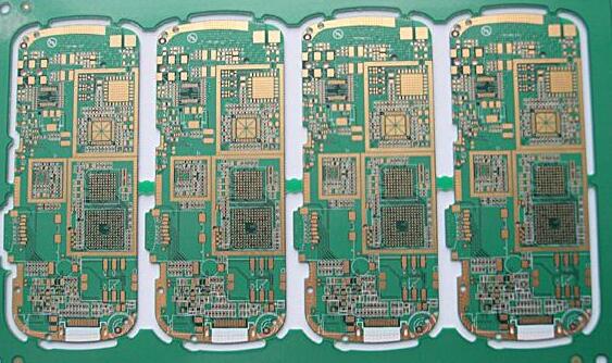
The PCB signal lines of the high current amplifier and SMPS must have the minimum resistance in order to minimize the I2R loss. Generally speaking, this means that 2 ounces of copper should be used and the signal lines should be as wide as possible. Figure 3 shows the signal lines of the TAS5261 reference design PCB board. In order to minimize the problems of EMI and audio performance, you should follow the configuration as much as possible, and apply this configuration to the high-voltage/high-power end of the power stage completely unchanged. The high-power signal line is located on the right side of the integrated circuit (IC) on the top layer (as indicated by the arrow). Figure 3 also shows the PCB configuration of the TAS5261 reference design.
The new high-wattage power stage of digital amplifiers helps to develop more diversified products and applications. The concepts described in this article can help overcome the main challenges encountered in high-power designs.