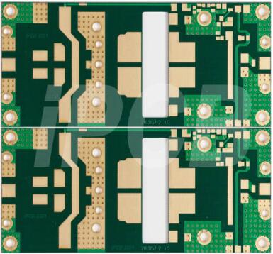
A weather radar is a type of weather radar that is the main tool for monitoring and warning of severe convective weather. The working principle of PCB weather radar is to emit a series of pulse electromagnetic waves, utilizing the scattering and absorption of electromagnetic waves by precipitation particles such as clouds, rain, and snow, to detect the spatial distribution and vertical structure of precipitation, and use it as a warning and tracking precipitation system.

PCB weather radar
The commonly used wavelengths for PCB weather radar are mostly in the range of 1-10cm. Because the attenuation of the 10cm wavelength is small, it is better to detect typhoons, rainstorms and hail. The commonly used domestically are domestically produced 713 mines (5.6cm), 714 radars (10cm), and 711 radars (3.2cm), which can detect weather systems within a range of several hundred kilometers around radar stations.
Advantages of PCB weather radar
1. PCB weather radar signals can penetrate materials such as clouds and rubber.
2. The PCB weather radar circuit can determine the speed, distance, and position of objects during movement.
3. The signals/pulses from PCB weather radar do not require media (wires) for transmission, as they can travel through space, water, and air.
4. PCB weather radar operates at high frequencies to save a large amount of data.
5. The signal from PCB weather radar can cover a large area without additional cost.
The basic components of PCB weather radar include:
1. Transmitter: The signal from the waveform generator is not strong enough for the radar. Therefore, the purpose of the transmitter is to amplify the signal using a power amplifier.
2. Receiver: The receiver uses a receiver processor (such as superheterodyne) to detect and process reflected signals.
Antenna: including parabolic reflector, planar array or electronically controlled phased array. It is responsible for sending and receiving pulses.
3. Duplexer: A duplexer is a device that enables an antenna to complete transmitter and receiver tasks. The working principle of a duplexer.
The working principle of PCB weather radar
PCB weather radar is an instrument used to detect weather phenomena such as precipitation, clouds, and storms in the atmosphere. Its basic working principle is to use radar beams to emit electromagnetic waves into the atmosphere. When these electromagnetic waves encounter substances such as water droplets and ice crystals in the atmosphere, they will undergo scattering and reflection. These reflected waves will be received by the receiver and converted into electrical signals. Through signal processing and analysis, information such as precipitation, clouds, storms, etc. in the atmosphere can be obtained.
The transmitter of PCB weather radar usually uses high-frequency electromagnetic waves with wavelengths ranging from 1 to 10 centimeters, which can penetrate clouds and precipitation without being absorbed or scattered. A radar transmitter emits electromagnetic waves into the atmosphere, which propagate in a certain direction to form a radar beam. When this radar beam encounters substances such as water droplets and ice crystals in the atmosphere, it undergoes scattering and reflection, which are received by the receiver and converted into electrical signals.
The receiver of PCB weather radar usually uses a highly sensitive receiver that can receive weak electrical signals. After receiving the reflected wave, the receiver converts it into an electrical signal and obtains information such as precipitation, clouds, storms, etc. in the atmosphere through signal processing and analysis. The process of signal processing and analysis includes steps such as filtering, denoising, demodulation, and demodulation. The final information obtained can be used to predict weather and formulate response measures.
The radar PCB can be described as an electronic circuit responsible for creating, transmitting, and receiving radio frequency signals. In addition, it also has an antenna structure installed in high-frequency laminated material, which transmits radar lobes generated by RF circuits.
In addition, the same antenna will receive reflected radar pulses once it hits a target and has been analyzed by the RF circuit. Usually, this modern radar circuit board will be equipped with digital circuits at the rear, which helps analyze any echoes, while the antenna and RF part is located at the front.
Key Elements of PCB Weather Radar
Range
The radar has an antenna that can transmit light-speed signals to the target. Once the target is hit, the signal will be reflected into the antenna. The distance between the object and the radar defines the distance. Usually, it is better to use a wider range because it allows users to reach distant goals.
Pulse repetition frequency
The transmission of radar signals must occur within all clock cycles, with appropriate delay intervals between these clock cycles. Ideally, the device should receive the echo of the signal before transmitting it to the next pulse. Similarly, the function of radar PCB is the same, sending periodic signals to form rectangular narrow pulse waves.
The delay between these two clock pulses will form the repetition time of the pulses. Considering this, the frequency of pulse repetition is the inverse of pulse repetition time n. This helps to determine the time when the radar PCB sends the signal.
Clarify maximum distance
Each clock pulse needs to transmit a signal. Moreover, the echo of the current clock pulse can only be received when there is a short interval between the current clock pulse and the next clock pulse. However, you will find that the target's range is shorter than normal. That's why you must choose the delay between these intervals wisely.
Usually, you must receive the echo of the current clock pulse before the next clock pulse is emitted. In this way, the signal will provide you with a very clear image and a view of the actual range of the object, which is the clear maximum range.
Minimum range
Contrary to this range, this minimum coverage range is the time it takes for the echo to reach the antenna after the initial transmission of the pulse width.
PCB weather radar plays an irreplaceable role in disaster weather monitoring and warning.