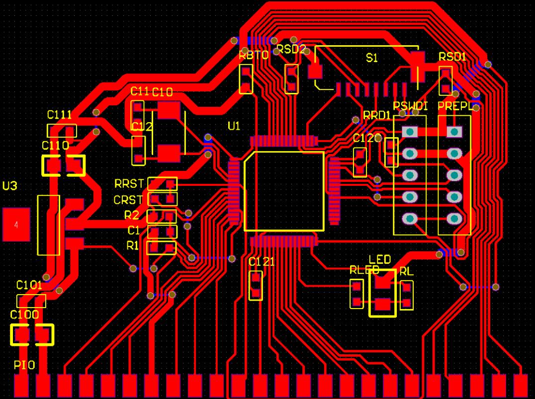
PCB design software can provide more intelligent rule setting and functionality, as well as design checks for reliability and manufacturability.

Commonly used software for PCB design
1. Protel
Protel is an EDA software launched by Altium in the late 1980s. Among the CAD software in the electronics industry, it is undoubtedly ranked ahead of many EDA software and is the preferred software for electronic designers.
2. Powerpcb
Powerpcb is a self laughing automation software for circuit design mainly promoted by MentorGraphics, and it is also one of the most widely used and best-performing EDA software in the field of Electronic engineering.
Software for designing and producing printed circuit board substrates, used in conjunction with PowerLogic, supporting multiple electronic components such as resistors, capacitors, and IC chips. PowerPCB is different from PSpice in that the latter can simulate line characteristics, while the former cannot.
3. Allegro
Allegro is an advanced PCB design wiring tool launched by Cadence. Allegro provides excellent and interactive work interfaces and powerful and comprehensive functions, combined with its front-end products Cadence, OrCAD, and Capture, providing the most perfect solution for high-speed, high-density, and multi-layer complex PCB design and wiring.
4. Orchard
Orcad is a set of Electronic design automation package software on personal computers, which is specially used for electronic engineers to design circuit diagrams and related diagrams, to design printed diagrams for printed circuit boards, and to simulate circuits.
5. EWB
EWB is an excellent circuit simulation software launched by Interactive Image Technologies Ltd in Canada in the early 1990s, specifically designed and simulated for electronic circuits.
Protel 99SE software
Protel 99SE is a circuit board design software developed by ProklTechnology based on the Windows environment.
The Protel 99SE consists of two main parts: advanced schematic design and advanced PCB design. The Advanced Schematic consists of two parts: the Circuit Diagram Editor (Schematic) and the Component Library Editor (Schematic Library).
Circuit schematic diagram
After entering Design Protel 99se, right-click "New" in Documents to create a "Schematic Document" file. Once opened, you can edit the circuit schematic diagram. First, locate and drag all components according to the already drawn circuit sketch into the edit box. Reduce the edit box and symmetrically arrange the components according to the circuit. Next, we can proceed with local wiring. Alternatively, you can first set up the various modules of the circuit, and then translate and combine them into a complete circuit by framing them. To cancel framing, you need to use Edit DeSelect Inside Area and then frame the previously selected modules with the mouse to remove them, as the modules change from yellow to normal color. The operation on a certain project is an operation on a database, so different databases will be opened in different windows. By minimizing the windows of each database, it can be seen.
Schematic Component Library
Although Protel itself contains a large component library, in practical applications, there are always situations where components cannot be found. Therefore, it is necessary to manually create this component in the component library based on component information. Another situation is that various components are scattered in the component library of various companies, making it difficult to use. Therefore, it is necessary to gather commonly used components into one component library, which requires making them yourself and copying frequently used components into this component library for future use.
basic operation
A component library file (. LIB) is also based on operations in a database file (DDB). Only components in a component library in the same database can be copied to each other through Tools - Copy Component. For different databases, the entire component library can be copied to the current database by right-clicking Copy, and then individual components can be copied from that database. When placing chip pins, the big head refers to the outer side of the pin, and the pin name will be embedded in the chip frame, with the PIN on the outer side.
1. When drawing a chip diagram, if the line drawing function is used, the View-Snap Grid function should be turned on to increase the positioning accuracy during line drawing.
2. When copying modules between different design files, the operation is as follows: first, select the part to be copied - copy, change the mouse to a crosshair, and then click the left button in the middle of the selected area - switch to another design file, and paste to complete the operation.
Printed Circuit Board (PCB) design software is an excellent tool for designing electronic device PCBs. By using PCB design software, engineers can not only solve problems related to Power integrity and signals, but also modify and improve the entire circuit structure.