


The application field of ceramic cooling heating PCB is gradually deepening and playing an important role.
Working principle of ceramic cooling heating PCB
A typical thermoelectric (TE) module consists of two ceramic substrates sandwiched between multiple pairs or "pairs" of bismuth antimonide bare sheets. Paired tube cores are electrically connected in series and thermally connected in parallel between ceramics. One type of ceramic is the "hot surface" and the other is the "cold surface".
is commonly used for manufacturing TE modules. They are ridged, thermally conductive, and excellent electrical insulators. In addition to providing a solid foundation, ceramics also insulate the electrical components inside the module from the heat sink on the hot side and the cooled objects on the cold side.
Metallization of ceramics is a component of the production of micro thermoelectric modules. Metallization is applied to ceramics to form internal junctions between BiTe columns and PN coupling within TEC. Thermoelectric coolers are common in the laser and optoelectronic industries. In many such applications, there is a ceramic substrate with end-customer electronic components (such as LD chips or APD arrays) for installation on the TEC cold side.
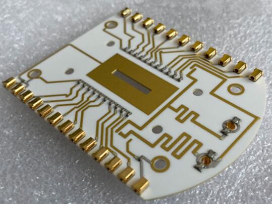
The solder pads of conductive materials are usually copper, which is just large enough to accommodate each of the many "paired" tube chips in the module, attached to the inner surface of the ceramic. Each of the P-type and N-type cores is electrically connected to each pad, with different pad layouts on the two ceramics to create a circuit with dice that twists and turns through the module. Usually, all pipe cores are welded in place to enhance electrical connections and secure the modules together. Most modules have an even number of P-type and N-type cores, each of which shares an electrical interconnection, known as a "pair".
Although both P-type and N-type materials are alloys of bismuth and tellurium, they have different free electron densities at the same temperature. P-shaped dice are composed of materials with insufficient electrons, while N-shaped dice are composed of materials with excess electrons. When current (amperes) flows up and down in the module, it attempts to establish a new balance in the material. The current considers P-type materials as hot junctions that require cooling, and N-type materials as cold junctions that require heating. As the material is actually at the same temperature, the result is that the hot end becomes hotter and the cold end becomes colder. The direction of the current will determine whether a specific chip is cooled or heated. In short, reversing polarity will switch between hot and cold sides.
The wires of the module are connected to the (copper) solder pads on the hot-end ceramic PCB. If the module is sealed, you can determine the hot end without power. Place the module on a flat surface and use the positive lead to point the lead toward you. Typically, the bottom of the red wire insulation on the right side will be the hot side.
With the gradual deepening of electronic technology in various application fields, the high integration of circuit boards has become an inevitable trend. Highly integrated packaging modules require good heat dissipation and bearing systems, while ceramic materials have good high-frequency and electrical properties, as well as high thermal conductivity, chemical stability, and thermal stability that organic substrates do not have, It is an ideal packaging material for the new generation of large-scale integrated circuits and power electronic modules. In the field of high-power LED lighting, metal and ceramic materials with good heat dissipation performance are often used to prepare circuit substrates.
However, in practical use, ceramic circuits themselves generate heat after being connected to the circuit. Long-term operation at high temperatures can accelerate the aging of the circuit and also easily damage the integrated circuit.
Working principle of ceramic cooling PCB
Ceramic refrigeration sheets are cooling devices composed of semiconductors, which have practical applications with the development of modern semiconductors, namely the invention of refrigerators.
Its working principle is that the DC power supply provides the energy required for the electron flow. After connecting to the power supply, the electron negative electrode starts passing through the P-type semiconductor, absorbs heat, and then reaches the N-type semiconductor, releasing heat. After passing through an NP module, heat is sent from one side to the other side, causing a temperature difference and forming a cold and hot end.
Working principle of ceramic heating PCB
Ceramic heating utilizes the electrical and thermal properties of special materials to convert electrical energy into thermal energy. Inside the ceramic chip, there is a special material called a "positive temperature coefficient thermistor PTC". This material can change the size of the resistance based on temperature changes, thereby achieving electric heating conversion. When an electric current passes through a ceramic sheet, it causes a thermal effect on the material, which generates heat on the surface of the ceramic sheet and dissipates it into the surrounding air. This thermal effect is controllable, and by adjusting the current size and time, the surface temperature of the ceramic sheet can reach a predetermined value and remain stable.
Moreover, ceramic sheets have excellent thermal conductivity, which can evenly distribute heat throughout the entire surface, resulting in uniform heating and avoiding the occurrence of hot and cold spots. In addition, the service life of ceramic chips is long, reaching tens of thousands of hours or even longer, and they are safe and reliable and are not prone to dangerous situations such as leakage.
The ceramic cooling heating PCB is determined by the direction of the current, switching between hot and cold.


