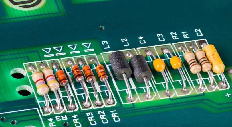
Resistance refers to the resistance that current encounters in a circuit, or the ability of an object to obstruct the current. The greater the resistance, the greater the resistance to current, and therefore the less current. On the contrary, the smaller the resistance, the less resistance the current is subjected to, and thus the greater the current. The symbol for resistance is' R '.

Resistance is a very important basic component in a circuit, which refers to the resistance that current encounters when passing through a certain material or device. Resistance is measured in ohms (Ω), and its value depends on the magnitude of the current and the properties of the material. In circuits, resistors are typically used to control the magnitude and direction of current, as well as to protect other circuit components from overload or short circuit damage.
The size of the resistance usually depends on the conductivity of the material. Metals usually have lower resistance because they have good conductivity while insulating materials typically have higher resistance. This is because insulation materials usually do not allow current to pass through, or only allow very small amounts of current to pass through.
The value of resistance can be measured using an ohmmeter or multimeter. An ohmmeter is an instrument specifically used for measuring resistance, which can directly read the value of the resistance. A multimeter is a universal measuring instrument that can be used to measure various parameters such as resistance, voltage, and current.
Resistance plays a role in limiting current, diverting current, dividing voltage, and reducing voltage in a circuit.
1. Current limiting
To ensure that the current passing through the electrical appliance does not exceed the rated value or the specified value required for actual operation, and to ensure the normal operation of the electrical appliance, a variable resistor can usually be connected in series in the circuit. When the size of this resistor is changed, the magnitude of the current also changes accordingly. We refer to this type of resistor that can limit the magnitude of current as a current-limiting resistor.
2. Diversion
When multiple appliances with different rated currents need to be connected simultaneously on the main circuit, a resistor can be connected in parallel at both ends of the appliances with lower rated currents, which serves as a "shunt".
3. Partial pressure
Generally, the rated voltage value is marked on the electrical appliance. If the power supply is higher than the rated voltage of the electrical appliance, the electrical appliance cannot be directly connected to the power supply. In this case, a suitable resistance value can be connected in series to the electrical appliance, allowing it to share a portion of the voltage so that the appliance can operate at the rated voltage. We call such a resistor a partial voltage resistor.
Factors affecting resistance
1. Length: When the material and cross-sectional area are the same, the longer the length of the conductor, the greater the resistance.
2. Cross-sectional area: When the material and length are the same, the smaller the cross-sectional area of the conductor, the greater the resistance.
3. Material: When the length and cross-sectional area are the same, the conductor resistance of different materials is different.
4. Temperature: For most conductors, the higher the temperature, the greater the resistance, such as metals; For a few conductors, the higher the temperature, the lower the resistance, such as carbon.
As the most basic component of electronic circuits, resistance are applied in various electronic circuits.