Radio frequency is abbreviated as RF. Radio frequency is radio frequency current, which is an abbreviation for high-frequency alternating current electromagnetic waves. Alternating current that changes less than 1000 times per second is called low-frequency current, and current that changes more than 10000 times is called high-frequency current, and radio frequency is such a high-frequency current.
Radio frequency refers to the modulated radio waves generated by radio frequency circuits at a specific frequency. The RF pcb refers to the part of the circuit that runs from the antenna (ANT) to the receiving and transmitting baseband signals (RXI/Q, TXI/Q).

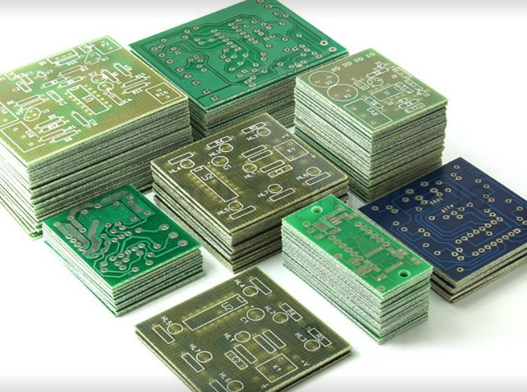
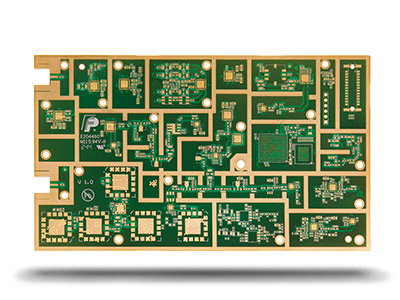
rf PCB
RF PCB is a special type of printed circuit board mainly used for high-frequency electronic devices. This kind of PCB needs to consider many factors, such as signal transmission, impedance control, signal integrity and EMC (electromagnetic compatibility). Engineers designing RF and microwave PCBs need to pay special attention to factors such as PCB materials, wiring, ground plane, antennas, filters, and PCB layout. PCB materials need to have high dielectric constant and low loss to improve the efficiency and accuracy of signal transmission. Cabling needs to be optimized to reduce signal reflection and loss, while also considering signal integrity and EMC issues. In order to reduce noise and interference, the ground plane must be designed and laid out correctly. Antennas and filters also need to consider the layout of PCBs and the selection of components.
RF PCB generally have the characteristics of high frequency and high performance, and usually choose substrates with high dielectric constant accuracy, stable characteristics, and low losses. In addition, the base material must be suitable for production processing, such as high-temperature reflow welding. The commonly used RF substrates currently include FR4, TACONIC, and ROGERS.
Standards for RF PCB
1: Low power RF RF circuit board, mainly using standard RF4 material, with good insulation and uniform material
2: In the early PCB design of RF pcb, each component should be tightly arranged to ensure the shortest connection between each component.
3: For a mixed signal PCB circuit board, the RF and analog parts should be separated from the digital part (this distance is usually more than 2cm and should be separated from the RF part)
In addition to the general principle of considering the current size, the printed wire on the RF PCB must also consider the characteristic impedance of the printed wire, and the impedance matching must be strictly carried out. The impedance control of the printed wire must be considered when making the PCB. The characteristic impedance of the printed wire is related to the material characteristics and physical parameters of the PCB, so PCB designers must know the performance of the PCB board.
When designing PCB at microwave frequencies, the key characteristics defining the properties of microwave/RF PCB laminates include dielectric constant (Dk), loss factor (Df), coefficient of thermal expansion (CTE), dielectric constant thermal coefficient (TCDk), and thermal conductivity.
Basic characteristics of PCB RF
Conceptually, wireless transmitters and receivers can be divided into two parts: fundamental frequency and radio frequency. The fundamental frequency includes the frequency range of the input signal of the transmitter and the frequency range of the output signal of the receiver. The bandwidth of the fundamental frequency determines the basic rate at which data can flow in the system. The fundamental frequency is used to improve the reliability of the data stream and reduce the load imposed by the transmitter on the transmission medium at a specific data transmission rate. Therefore, when designing fundamental frequency circuits for PCB RF, a large amount of signal processing engineering knowledge is required.
The RF pcb of the transmitter can convert and upshift the processed fundamental frequency signal to a designated channel, and inject this signal into the transmission medium. On the contrary, the RF circuit of the receiver can obtain signals from the transmission medium, convert and reduce them to the fundamental frequency.
When selecting RF PCB materials, the dielectric constant, loss factor, coefficient of thermal expansion, dielectric constant, thermal coefficient and thermal conductivity should be comprehensively considered.