When designing HDI circuit boards, we must first follow the IPC guidelines and standards. Four specially suitable for HDI circuit board design
IPC/JPCA-2315: This is an overview of HDI and provides a model for estimating design density.
IPC-2226: This specification educates users on microvia formation, wiring density selection, design rule selection, interconnect structure and material characterization. It aims to provide standards for the design of printed circuit boards using microvia technology.
IPC-4104: This standard determines the materials used in high-density interconnect structures. The IPC-4104 HDI material specification includes a slash, which defines many thin materials for HDI. The material properties of the slash board are divided into three main material types: dielectric insulator (IN); conductor (CD) and conductor and insulator (CI).
IPC6016: This document covers the performance and certification of high-density structures.

Blind holes can be "shifted or swung" in XY or θ() angles to create more wiring space
blind holes can be placed on the inner layer (3D) to further create more breakthrough space
The center distance can be changed on the inner layer to provide extra space for the trace.
"If all of this happens on or near the primary side, then space for traces will be created under the BGA on the secondary side, or it will be more important for discrete devices such as decoupling capacitors.
If you study the first principle and ask yourself, "What does my via do?". The answer is that the most common vias on PWB are GND vias. "The second most common channel?" The answer is obvious, it is the PWR channel. Therefore, moving the GND plane, which is usually the second layer, to the surface provides an opportunity to eliminate all these vias to GND. Similarly, moving the most commonly used PWR plane to layer 2 will replace those TH with blind vias. Compared with traditional "microstrip" stacks, they provide four (4) advantages, as shown in Figure 7:
There are no fine lines for plating or etching on the surface.
The surface can be uninterrupted GND pouring to reduce EMI and RFI (Faraday cage)
The closer layer 2 (PWR) to layer 1 (GND), the more plane capacitance is available, the lower the PDN plane inductance.
The energy stored in the planar capacitor can be delivered to the element with the lowest series inductance, thereby eliminating most of the decoupling capacitors.
Blind holes are placed to open larger boulevards
A useful HDI design technique is to use blind vias to open up more routing space on the inner layer. By using blind holes between the through holes, the routing space is effectively doubled in the inner layer
allows more traces to connect to the pins on the internal rows of the BGA. As shown in Figure 6, for this 1.0 mm BGA, only two traces can escape between the through holes on the surface. But under the blind hole, there are now six traces that can escape, and the routing is increased by 30%. Using this technology, a quarter of the signal layer is required to connect complex high I/O BGAs. Blind holes are arranged to form a tree-lined avenue that spans, L-shaped or diagonal. Which configuration is used is driven by the power and ground pin assignments. This is why for FPGAs, reprogramming the position of the power and ground pins can be very efficient
Blind vias can be used to form boulevards in the inner layer, allowing 30% of the path to flow out of the BGA. If the through hole is placed in the center of the BGA pad and there is no filling, when the solder paste is applied to the pad and the BGA is placed When on the pad, during reflow, when the solder melts, the BGA ball falls and traps any air that may be present, like a "cork in a bottle." By "off-center" the through hole, when the solder melts and flows into the micro hole, air has a chance to escape.
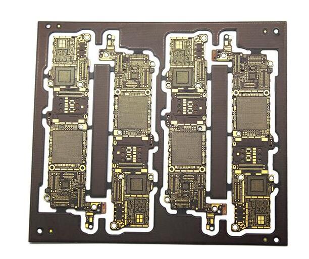
HDI circuit boards are high-precision circuit boards, usually used in high-precision instruments and equipment, such as mobile phones, aerospace technology, etc.