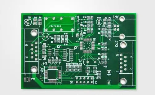
In PCB design, especially in high-frequency circuits, some irregular and abnormal phenomena are often encountered due to ground interference. This article analyzes the cause of the ground wire interference, introduces the three types of ground wire interference in detail, and proposes solutions based on the experience in practical applications. These anti-jamming methods have achieved good results in practical applications, enabling some systems to run successfully on site. In a single-chip microcomputer system, PCB (printed circuit board) is an important component used to support circuit components and provide electrical connections between circuit components and devices. PCB wires are mostly copper wires, and the physical properties of copper also lead to electrical conductivity. There must be a certain impedance in the process. The inductance component in the wire will affect the transmission of the voltage signal, and the resistance component will affect the transmission of the current signal. The influence of the inductance in the high-frequency line is particularly serious. Therefore, it is necessary to pay attention to and Eliminate the impact of ground impedance.

1 The cause of interference
Resistance and impedance are two different concepts. Resistance refers to the impedance of the wire to the current in the DC state, and impedance refers to the impedance of the wire to the current in the AC state, this impedance is mainly caused by the inductance of the wire. Because the ground wire always has impedance, when measuring the ground wire with a multimeter, the resistance of the ground wire is generally mmΩ.
Take a section of wire 10 cm long, 1.5 mm wide, and 50 μm thick on the PCB as an example. The impedance can be calculated by calculation. R=ρL/s (Ω), where L is the wire length (m), s is the wire cross-sectional area (mm2), ρ is the resistivity ρ=0.02, so the wire resistance is about 0.026 Ω.
When a piece of wire is far away from other wires and its length is much larger than its width, the self-inductance of the wire is 0.8 μH/m, then the inductance of a 10 cm long wire is 0.08 μH. Then calculate the wire inductance by the following formula: XL=2πfL, where f is the frequency of the wire passing signal (Hz), and L is the self-inductance per unit length of the wire (H). So respectively calculate the inductance value of the wire at low frequency and high frequency:
In actual circuits, the signal that causes electromagnetic interference is often a pulse signal. The pulse signal contains rich high-frequency components, so a relatively large voltage will be generated on the ground. It can be seen from the above formula calculation that the wire resistance is greater than the wire inductance in low-frequency signal transmission. For digital circuits, the working frequency of the circuit is very high. In high-frequency signals, the wire inductance is much greater than the wire resistance. Therefore, the ground impedance has a considerable impact on digital circuits. This is the reason why a large voltage drop occurs when the current flows through a small resistance, which causes the circuit to work abnormally.
The above is the introduction of PCB ground wire interference analysis. Ipcb is also provided to PCB manufacturers and PCB manufacturing technology.