As an important link in hardware design, PCB Layout is an absolutely important indicator that affects performance when the hardware circuit design is reasonable. Many PCB Layout engineers complete the layout and routing according to the constraint rules given by hardware engineers or PI SI engineers. These are commonly known as "wire pullers". They repeat and mechanically complete a piece of PCB Layout. After a while, some of them may have some experience: which should be equal in length, which should be thicker, which should be parallel, ensure proper line spacing, etc. . However, they relied on so-called experience, and many of them knew it and did not know why. I think that if you want to make a breakthrough, you must broaden your knowledge. That is, PCB Layout engineers cannot let others treat themselves as "wire pullers".
First of all, you must have a certain circuit understanding ability (of course, the design ability like a hardware engineer is not necessary, if you can, it is best);
Secondly, it is necessary to have the ability of SI/PI engineers to do PI/SI analysis (of course, it is not necessary to have the ability of RF simulation, if it can, it is best). With this knowledge, you will not only have the ability to design a good PCB, but also have the theoretical capital for hardware and SI/PI engineers, and you can even give their circuit design suggestions from the PCB design.

Not much to say, some principles summarized from some PCB designs:
1. About the layout
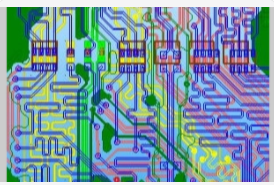
1. Layout is to place circuit components reasonably. What kind of placement is reasonable. A simple principle is that the modularization is clear, which means that people with a certain circuit foundation can see which piece is used to achieve what function when they get your PCB.
2. Specific design steps: First, generate the initial PCB file according to the schematic diagram, complete the pre-layout of the PCB, determine a relative PCB Layout area, and then tell the structure that the structure is based on the area we give, and then based on the overall structure design, Give specific constraints.
3. According to the constraints of the structure, complete the drawing of the board edges, positioning openings and some forbidden areas, and then complete the placement of the connectors.
4. The principle of component placement: Under normal circumstances, the main control MCU is placed in the center of the board, and then the interface circuit is placed close to the interface (such as network port, USB, VGA, etc.), and most of the interfaces have ESD protection. There is filtering processing. The principle followed is to protect first and then filter.
5. Then there is the power module. Generally, the main power module is placed at the power inlet (such as the system 5V), and the discrete power module (such as the 2.5V power supply of the module circuit) can be placed in a denser place with the same power network according to the actual situation.
6. Some internal circuits are not led to the connector. We generally follow this basic principle: high-speed and low-speed sub-regions, analog and digital sub-regions, interference sources and sensitive receptors sub-regions.
7. Then for a single circuit module, follow the current flow direction when designing the circuit.
The overall circuit layout is probably like this, and you are welcome to add and correct me.
Two, about wiring
1. Wiring, the most basic requirement is to ensure that all networks are effectively connected. Connectivity is very easy to achieve, and effectiveness is a rather vague concept. In fact, there are two kinds of signals in the circuit: digital signals and analog signals. For digital circuits, it is to ensure sufficient noise tolerance, and for analog signals, try to achieve zero loss.
2. Before wiring, it is generally necessary to understand the entire PCB stack design, that is, plan all wiring layers as: optimal wiring layer and sub-optimal wiring layer. . . ., The optimal wiring layer, that is, the complete ground plane of the adjacent interview. This layer is generally used to route important signals (including all signals in DDR, differential signals, analog signals, etc.). Other signals (I2C, UART, SPI, GPIO) go to other layers, and ensure that only relevant signals of this circuit exist in important areas (such as DDR, network port, etc.)
3. Then when high-speed signal wiring, reflection, crosstalk, EMC and other issues need to be considered, so impedance matching is generally required, such as single line 50R, differential line 100R, etc., depending on the actual design (the principle is to ensure that the impedance is equal and continuous), Crosstalk mainly considers the 3W/2W principle, packet land processing and so on.
4. For the power supply and power circuit, first of all, it is necessary to ensure sufficient load capacity, that is, the entire return path of the power supply is as thick and short as possible. From the EMC point of view, the return flow is a loop to form a loop antenna and radiate to the outside. It is possible to reduce the loop area.
The overall circuit layout is like this, welcome to add and correct.
Three, about the land
1. Grounding and grounding design is a very important part in PCB design, because the ground is an important reference plane. If there is a problem with the ground plane design, other signals will not be stable.
2. The ground is generally divided into chassis ground and system ground. As the name suggests, the chassis ground is the ground to which the sheet metal of the product is connected, and the system ground serves as the reference plane of the entire circuit system.
3. The actual principle of the general system ground and the chassis is: the chassis ground and the system ground are separated, and then the system ground is connected at a single point or multiple points through a magnetic bead and a high-voltage capacitor.
4. Regarding the system ground: functionally divided into digital ground, analog ground, and power ground. (There has been controversy about the division of land. I am here.)
First of all, when the layout is very reasonable, I think the ground can be divided. The layout is very reasonable, that is, the digital area has only digital signals, the analog area has only analog signals, and the power area has only power signals, and there is a complete ground plane under them. Because current and water flow are very similar, they both flow to low places, and there is a complete ground plane below them. Therefore, from the shortest and lowest principle, they flow back directly underneath, instead of fleeing to other places.
However, sometimes, it is not so ideal, and there are some crossovers in each area. At this time, you generally choose a single point of understanding and use 0R resistors (magnetic beads are not recommended, because magnetic beads have a filtering effect at high frequencies). The placement of the resistors is close to the densest place where the crossover area is the smallest.