In addition to the scale effect of automated production, SMT also has the following technical advantages: components can be mounted on both sides of the PCB to achieve high-density assembly; even the smallest size components can be precisely mounted, so high quality can be produced PCB components.
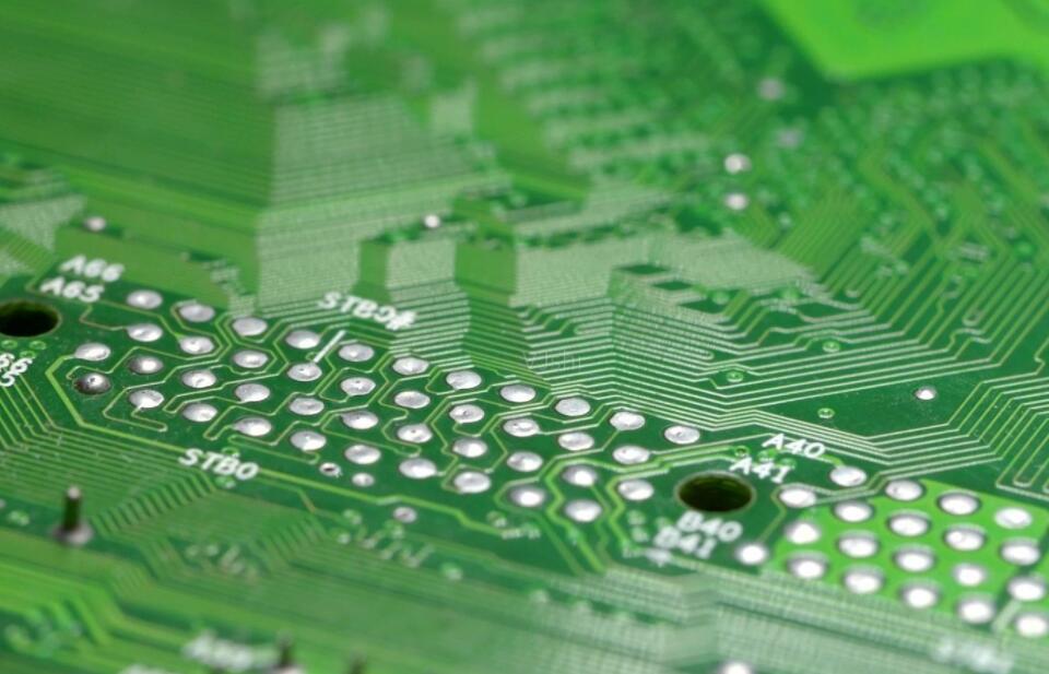
However, in some cases, these advantages diminish as the adhesion of components on the PCB decreases. Let us observe the example in Figure 1. SMT components are characterized by compact design and easy mounting. They are significantly different from through-hole connectors in size and assembly form.
The PCB assembled with SMT components (left) and a Dali through-hole connector (right)
Connectors used for field wiring in the industrial field are usually high-power components. It can meet the needs of transmitting high voltage and large current. Therefore, sufficient electrical clearance and creepage distance must be considered when designing. These factors ultimately affect the size of the component.
In addition, the convenience of operation and the mechanical strength of the connector are also very important factors. The connector is usually the "interface" for the communication between the PCB motherboard and the "external components", so it may sometimes encounter considerable external forces. Components assembled by through-hole technology are much higher in reliability than corresponding SMT components. Whether it is strong pulling, squeezing or thermal shock, it can withstand, and it is not easy to leave the PCB.
From cost considerations, SMT components on most PCBs account for about 80%, and production costs only account for 60%; through-hole components account for about 20%, but production costs account for 40%, as shown in Figure 2. It can be seen that the production cost of through-hole components is relatively high. For many manufacturing companies, one of the future challenges is to develop printed circuit boards using pure SMT technology.

PCB with through-hole parts and SMT components
According to the production cost and the impact on the PCB, the existing processes such as SMT + wave soldering and SMT + press in technology (press in) are not completely satisfactory, because the existing SMT process requires secondary processing and cannot be completed at one time Assembly.
This puts forward the following requirements for components using through-hole technology: through-hole components and patch components should use the same time, equipment, and methods to complete assembly.
How to integrate THR with SMT
The technology developed according to the above requirements is called through-hole reflow (THR), also called "pin inpaste (PIP)" process, the process of through-hole reflow soldering technology
The "lead immersion solder paste" method applies a typical SMT production process to PCBs with plated through holes, and has achieved satisfactory results. However, when using this method, the relevant parameters need to be adjusted according to the actual components used and the specific conditions in the processing process.
The characteristics that the connector components that can adopt the THR process should meet
Steps to complete the THR process
1. Confirm whether the through-hole connector can adopt THR process
"True" THR connector components should meet the characteristics.
2. PCB design needs to adapt to new process conditions
1) Aperture
There are two principles of aperture selection: on the one hand, it should ensure that the solder reflows easily into the solder hole (capillary principle), on the other hand, it should also ensure the reliability of assembly (component tolerance), and the choice of aperture
2) The design of the pad ring
The recommended pad ring width is 0.5mm, as shown in Figure 6, which facilitates the evaluation of the formed solder joint meniscus. If a larger spacing and creepage distance are used, according to the above process, the width of the pad ring is only 0.2mm.
3. The appearance of high-quality solder joints
THR is an independent welding process, and the quality of solder joints can be inspected in accordance with the IPC-A-610C standard. Comparing the solder joints formed by wave soldering with the THR solder joints, according to the traditional standard, the THR solder joints appear to be "insufficient in tin" and have only a small meniscus. This phenomenon is a characteristic of the THR welding process, and the quality assurance department should usually determine whether it meets the welding requirements.
Pad ring design
4. Use template design suitable for THR process and pressure applied to solder paste
The thickness of the standard template is 150~120μm, and there is usually no need to apply excessive coating pressure.
ds=di+2R-0.1 (di is the aperture, R is the width of the pad ring)
This formula guarantees proper contact between the pad ring and the template, and the pressure on the solder paste is sufficient, without increasing the number of times the template is cleaned.
The characteristics of solder paste require the following points: during the coating process, it should have good fluidity, good wettability, and good adhesion in the hole and when installing the pins.
The characteristics of THR solder paste coating pressure
The products provided by most solder paste manufacturers can meet this process, the basic rule is still: SMT components determine the process window-THR process must also be adapted to it.
5. Apply enough solder paste on the PCB pads
The ideal THR solder paste coating pressure has the characteristics shown in Figure 7. The amount of solder paste applied on each pad must be twice the volume of the corresponding solder hole.
The required amount of solder paste must be in the form of "droplets" under the PCB. The amount of solder paste filled can be obtained by adjusting the printing speed and the squeegee angle. For example, by changing the angle of the squeegee, more pressure can be applied to the solder paste, as shown in Figure 8 (assuming the speed is constant).
Change the angle of the scraper
Another method is the closed coating method. The sealed solder paste coating system can directly apply pressure to the solder paste. By adjusting the pressure applied to it to obtain the required amount of solder paste applied,
Closed coating method
Both methods can achieve good results in production practice. However, due to the different production conditions, occasionally insufficient solder paste may be applied. In this case, the following improvement measures can be selected: the thickness of the template used is the maximum allowable value, the solder paste is repeatedly applied, the amount of solder paste is increased locally, the solder paste is applied on both sides (double-sided reflow soldering), and the coating is increased For pressure, use smaller tolerances (process standards usually specify the tolerance range).
6Choose the most optimized packaging form
"Tape packaging" is widely used in SMT processing. THR process connectors also use this standard packaging form. The width of the braid is generally between 32mm and 88mm.
THR products are suitable for most standard feeders. However, for some components, especially vertical components, it is necessary to check the radius provided by the feeder, that is, to check whether it is suitable at the feed and discharge points.
Many machines also have the function of processing waffle tray or tube packaging components, which can meet various needs, including dedicated or "unfinished" components.
7. Check the welding condition according to the standard IPC-A-610C
The THR connector can be tested according to the IPC-A-610C standard. As long as the pins have protruding parts on the PCB, the solder joints on the soldering surface can be evaluated.
How to reduce production cost through THR process
A key issue that affects the use of THR technology is to find the balance between production cost (low) and component cost (high). The reason why THR connectors are more expensive than standard components is due to higher material costs and packaging costs.
The potential cost reduction depends on the production process. The influencing factors are as follows: the degree of production automation, order volume, whether other through-hole components can be replaced, the need to design new products or redesign existing products.
Not all manufacturers recommend the use of THR process connectors. But if all the components except your PCB connector have implemented the SMT process, then products using THR technology are undoubtedly your best choice.