Analysis of Two Major Reasons for FPC Broken
To know these two reasons, you have to analyze from Kaboer's professional design, leave enough hinge space, and fpc can't be too hard.
1. The fpc is too short.
2. The material is too hard, it may be better if you change to a softer material, 100,000 turns are not a problem.
There is another point. Fpc breaking is the initial problem. I personally think that this problem is not very difficult. The most terrible thing is fpc noise. Eliminate the interference between fpc and vias. What good ways do you have for fpc noise? There are generally several problems caused by fpc: breaks cause LCD not to display and clamshell abnormal sound; for breaks, most of the design length is too short, and the hole gap structure design at the fpc is not reasonable, and clamshell abnormal sound often occurs. It is the fpc and the shell wall contacting and scratching. In short, the fpc must be repeatedly tried several times to design it in place. It is best to use a transparent shell, or cut the shell, observe more, and then make design improvements.
Of course, some PCB manufacturers had no problems when they first started proofing, but later mass production had problems, so you must see if it was a material problem.
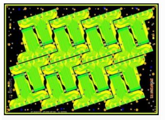
(1) Analyzing the broken FPC picture first, it can be seen that:

1. The fracture is the electromagnetic shielding layer of the FPC outer layer
2. It can be seen from the figure that this layer is folded from the back of the product in the swing area, so it is judged that this layer is made separately and then attached to the FPC product.
(2) Speculation of the cause of the fracture:
1. The shielding layer is solid copper on the whole surface, which has a high hardness, which increases the possibility of fracture during the swing process.
2. The shielding layer is attached to the FPC separately, and is not a tight whole with the FPC product. During the swing process, it will deviate from the originally set bending direction, which may lead to excessive stress concentration and breakage.
(Therefore, the FPC material problem mentioned by lbmouse is excluded as the direct cause of the fracture. In addition, there is no corresponding information on the structural problem, so we will not discuss it for the time being)
(3) Suggestions:
1. Wrap the tape around the break and bind it to the FPC to increase its tightness with the FPC.
2. Change the copper surface of the shielding layer to a grid to reduce the hardness.
1. Long-term recommendations:
For the shielding layer of the FPC swing zone, the use of printed or coated conductors, or the bonding of conductive cloth dedicated for FPC electromagnetic shielding, will completely avoid the problem of shielding breakage, and the cost will not increase.
The above is my personal suggestion. I don’t know if you have any comments.
FPC can design a tear-proof line, and Korean mobile phones have tear lines. Last time our company switched to domestic production of mobile phones, domestic manufacturers began to have problems, and later the tear line was added and there was no problem at all. There is also DOME outsourcing a protective film to prevent moisture and dust from entering!
Change the copper layer of the FPC to a copper mesh and increase the deflection of the FPC. This should be solved, but for the bundling, it is recommended to do it as a last resort. For the fracture in this picture, I personally think that the attention is caused by the pulling, that is, the fpc is too short, and there is the problem of the fpc via hole, which is mainly caused by the mechanism of the plastic shell.
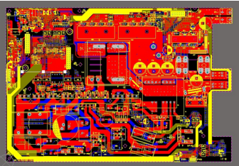
This is a hollow structure, referring to the bend of the mobile phone motherboard.
This is caused by twisting when turning over. The FPC at B-B in the figure (right) should be moved to the middle, and the length of torsion deformation can be increased to reduce the possibility of fracture.
fpc shielding is now a lot of useful aluminum foil, the flip cover will be better;
I think the most important thing for fpc design is to reduce stress concentration. The rounded corners must be as large as possible. In many cases, the internal rounded corners of the fpc are broken. Increasing the rounded corners will make a big improvement. Do not have the two ends of the shaft. Obvious stress generation (just as someone said before that the connector should not be too close to the lead-out part of the shaft, the adhesive layer at both ends of the fpc will generate a lot of torsion);
fpc also has its own torsion. A longer axial length of the shaft will weaken its own torsion, but if it is too long, there will be obvious layer-to-layer flapping noise;
The fpc supplier is also a very important part. There are electrolytic copper and rolled copper on the fpc copper wire. Among them, the life of electrolytic copper is relatively low, which may affect the test;
The length simulation of fpc is very important.
In fact, the life of the FPC is also related to the chassis structure. Because of the frequent need for activities and the limited space in the case, the FPC will inevitably come into contact with the hard case. The flip is not so obvious yet, but not so on the canopy phone.
Quality and price are inseparable. However, the value of a single FPC is relatively low, but the original components on the board are not cheap. In addition, if damaged during the warranty period, the warranty cost is much higher than the value of the FPC.