How to determine the number of PCB connected boards
Generally speaking, after the design engineer has finalized the appearance and shape of the printed circuit board (Printed Circuit Board), they should immediately proceed to the plywood/joint board/panelization of the circuit board. The purpose of connecting the board is nothing more than the following purposes:
1. Increase the output of the production line.
2. Reduce the loss of plates.
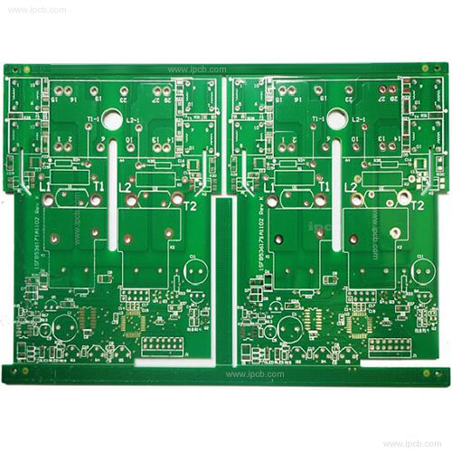
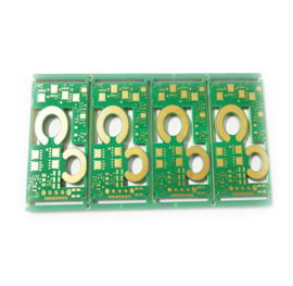
The most common connecting board usually combines two or more pieces of the same circuit board into a large circuit board, such as 2 in 1 (two in one), 3 in 1 (three in one), 4 in 1 (four in one), etc. . It is also possible to combine circuit boards of different shapes into a large board, but it is rare because it is difficult for "Planners" to arrange production to match the exact number of different boards.
More related reading: The benefits of using "yin and yang boards" for PCB

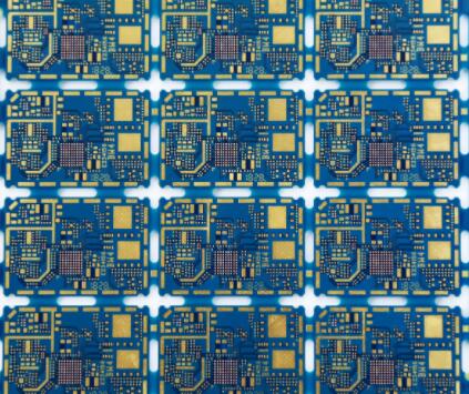
There are also examples of making the same board into a [Yin-Yang board]. [Yin-Yang board] mostly means top and bottom side configurations. This is usually used on circuit boards with fewer parts, such as mobile phone boards, because they can Make full use of SMT's long-term boarding function to increase efficiency, but the disadvantage is that it is limited in use and may cause uneven heating of parts. For example, some circuit boards will concentrate heavier parts on one side, and then this One side will be used as the second part to avoid the heavy parts from falling after repeated reflow soldering. Of course, this kind of board is more difficult to adopt the "Yin-Yang board" design.
Some boards may have more heat-absorbing parts (such as large-area ATM card reader slots), which is not suitable for the design of "Yin-Yang board". Of course, there is also a flexible [yin-yang board] playing method that can overcome this problem, but I won't discuss it here.
Basically, when designing how many connecting boards, the following factors should be considered. In fact, no matter how it is produced or designed, it is ultimately inseparable from the consideration of money. Therefore, all factors should be converted into amounts for the final measurement of the standard to be selected. A suitable method of jigsaw puzzle.
Consider the best usage rate of circuit boards
In order to quickly mass produce and reduce costs, general PCB manufacturers will have their basic standard board sizes, such as 16.16"x16.16", 18.32"x18.32", 20.32"x20.32", etc. We want What we do is to use up all these plates as much as possible, that is to say, we must choose a suitable standard plate size to stuff our plates in to achieve the highest utilization rate of the plates.
Because the PCB price will be priced according to the size of the board, the more boards that can be packed in a board, the cheaper the price of the board. Of course, the price of the circuit board has to consider the number of layers of the board, how many holes to drill, whether there is HDI... etc.
Consider PCB production/placement efficiency
PCB lines usually have the so-called long line and short line. The short line means the line is shorter. Most of them only have a fast machine and a slow machine. At most, one more fast machine is added; the long line means the line is longer, the fast machine and the slower There are a few more speed machines. But no matter the length of the line, there will always be a solder paste printing machine. Generally speaking, taking a plywood with a board length of 150mm as an example, it takes about 35-40 seconds to print the solder paste once. If only 2 in 1 plywood is used for input SMT is short-term, so the time allocated for each machine may be about 10 to 26 seconds. Obviously, the time is all lower than the time of solder paste printing, that is to say, the subsequent placement machines are waiting for the solder paste printing machine. This results in idle SMT machines and reduces production capacity.
If the 2 in 1 connecting plate is changed to 4 in 1, then the efficiency will be improved immediately (output per hour)
1. Hourly output: {[60(sec/min) x 60(min/hour)] / bottleneck time (sec)} x number of plywood.
In addition, PCB manufacturers prefer to have as few as possible the number of connected boards, because this can avoid the so-called cross board (X-board) loss. The so-called cross board is a bad board with more than one board in the plywood. The general SMT manufacturing factory does not want to accept this kind of board, because it will cause a loss of efficiency, but this kind of circuit board cannot be absolutely avoided in the manufacturing process, so even the board The more the number, the more the number of scrapped circuit board factories will be, and the relative cost will increase.
As mentioned at the beginning, the final result has to be converted into money to calculate the optimal number of plates to be used and connected. And the results may be different for different board factories and different PCB factories.
Secondly, you also need to consider that the V-cut or router process should be used to remove the edge of the board after the PCB composition. These will also affect the design of the connecting board. There is a chance to discuss it.