Inspection preparation: The inspector must wear anti-static gloves and a wrist watch, and prepare tools such as calipers and electrical performance parameter instruments.
1. Technical requirements
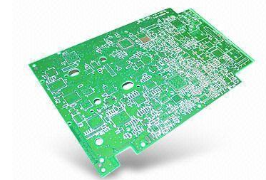
1.1 PCBA component plates must be made of materials above 94-V0 flame retardant grade, and have corresponding UL yellow cards;
1.2 The appearance of the PCBA component sheet has no rough burrs, poor cutting, delamination and cracking, etc.;
1.3 PCBA component plate size, aperture and edge distance meet the requirements of engineering drawings, and the unmarked tolerance value is ±0.1mm; unless required, the plate thickness is 1.6±0.1mm;
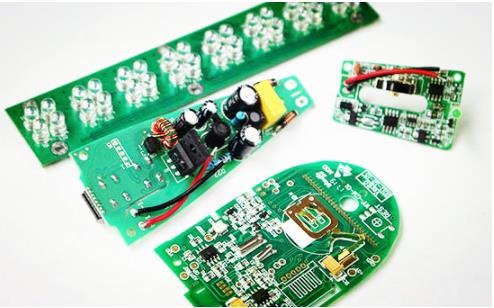
1.4 PCBA components must print the production (design) date, UL symbol, certificate number, 94V-0 characters, factory logo, product model; if the PCBA component consists of multiple PCB boards, the rest of the PCB boards should also print the above content;

1.5 The printed character number and font size should be clear and identifiable as the principle;
1.6 If PCBA components use a resistance-capacitance step-down circuit, a half-wave rectifier circuit must be used to improve the safety and stability of the circuit;
1.7 If the PCBA component adopts a switching power supply circuit, the standby power consumption must be less than 0.5W;
1.8 The standby power consumption of European products using PCBA must be less than 1W. If the US version PCBA customers have special requirements, the standby power consumption shall be implemented in accordance with the technical requirements;
1.9 Except the φ5 amber high-brightness astigmatism used for the power supply lamp, the luminous tube uses all-green or all-red φ3 high-brightness astigmatism;
1.10 PCBA components stipulate live wire (ACL), neutral wire (ACN), relay common terminal wire (ACL1), high-grade or continuous wire (HI), low-grade wire LO;
1.11 The welding fuse and CBB capacitor (resistance-capacitance circuit) of PCBA components must be on the live wire (ACL);
1.12 ACL1 must be connected to the live wire, HI or LO connected to each end of the heating element, and the common end of the heating element must be connected to the neutral line;
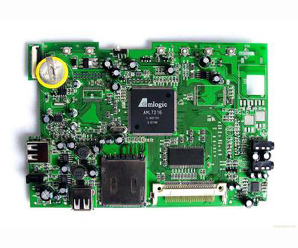
1.13 The solder joints of PCBA components must not have false soldering, continuous soldering, desoldering, and the soldering joints are smooth, uniform, free of bubbles, pinholes, etc.
2. Selection of components
2.1 The components of PCBA components are preferred to use well-known brand manufacturers, followed by manufacturers that meet international standards or industry standards; manufacturers’ components that do not use corporate standards;
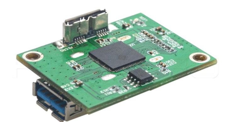
2.2 Use industrial-grade IC for integrated block components (IC);
2.3 Connecting plug-ins and terminals must have UL certification and provide certificates;
2.4 The resistor components are made of metal film resistors with a clear color circle, and the manufacturer complies with industry standards;
2.5 Electrolytic capacitor components use explosion-proof capacitors with a working temperature of -40-105 degree Celsius, and the manufacturer complies with industry standards;
2.6 Crystal components should be used for crystal oscillator components. RC or chip built-in is not recommended. Manufacturers comply with international standards;
2.7 The diodes or transistors are selected from domestic well-known brands, which conform to industry standards;
2.8 The dump switch adopts infrared photoelectric type instead of mechanical type;
2.9 The surface of the designated components must be printed with UL/VDE/CQC/symbols, trademarks, parameters, etc. and clearly visible;
2.10 The relevant wires must have UL/VDE symbols, wire gauges, certification numbers and manufacturer names, etc., and are clearly visible;
3. Test and inspection
3.1 The PCBA components are installed on the corresponding test tooling table, and the suitable voltage frequency and other parameters are adjusted;
3.2 Whether the self-inspection function of PCBA components meets the requirements of the functional specification, whether the relay output has abnormal noise, and whether the LEDs are all on evenly;
3.3 Whether the placement of the PCBA component dumping device and the output function during dumping comply with the functional specification;
3.4 When the temperature probe of the PCBA component is disconnected and short-circuited, whether the output function and fault indication comply with the functional specification;
3.5 Whether the function output of each button of the PCBA component meets the requirements of the function specification;
3.6 The ambient temperature of PCBA components indicates whether the temperature displayed by the LED or digital tube complies with the functional specification;
3.7 The power status of the PCBA component indicates whether the LED complies with the functional specification;
3.8 Whether the intelligent control operation mode of PCBA components meets the functional specifications;
3.9 Whether the continuous operation mode of PCBA components meets the functional specifications;
3.10 Whether the standby power consumption of PCBA components meets the functional specifications;
3.11 The voltage is adjusted to 80% of the rated voltage, whether the relay output has abnormal noise, and whether the LED brightness is uniform;
3.12 The voltage is adjusted to 1.24 times of the rated voltage, whether the relay output has abnormal noise, and whether the LED brightness is uniform.