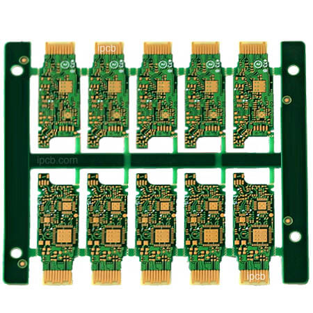
Causes of failure of blind via interconnection of HDI board
1. Excessive energy during laser ablation
Laser ablation method is currently the main production process for making blind holes. Although CO2 laser cannot directly ablate the copper layer, if the copper layer is specially treated to make its surface have the characteristics of strong infrared wavelength absorption, it will make the copper layer quickly raise to a very high temperature. The inner layer of copper at the bottom of the blind hole is generally browned, because the browned copper surface reflects less laser light, and its rough surface structure increases the diffuse reflection of light, there by increasing the absorption of light waves, And the surface of the brown copper box is an organic layer structure, which can also promote light absorption. Therefore, if the laser energy is too large after laser drilling, it may recrystallize the inner copper surface layer at the bottom of the blind hole, causing changes in the inner copper structure.

2. Desmear is not clean
Removal of epoxy drilling or slag removal is an extremely important process before blind hole electroplating, which plays a vital role in the reliability of the connection between the copper of the hole wall and the inner layer of copper. Because a thin resin layer may make the blind hole in a semi-conductive state. During the E-TEST test, it may pass the test due to the stylus pressure, and problems such as open circuit or contact failure may occur after the board is assembled. However, taking the mobile phone board as an example, there are about 70 to 100,000 blind holes on each board, and it is inevitable that there will be occasional errors when removing the glue.
As the current cavitation potion systems of various manufacturers have been perfected, only by closely monitoring the bath liquid and immediately replacing the bath liquid before any problems can ensure the due yield.
3. The quality of the copper plating layer on the surface of the inner connecting plate is abnormal
The abnormal quality of the copper-plated layer on the surface of the inner connecting pad is also a reason for the blind hole ICD, because the physical properties of the copper-plated layer, such as ductility, tensile strength, internal stress, and compactness, play an important role in the reliability of the blind hole. Plays an important role, and the physical properties of the copper plating layer depends on the structure and chemical composition of the copper layer. The picture shows the ICD caused by the rough plating on the surface of the inner layer at the bottom of the blind hole. The copper surface of such an inner layer is easy to cause unclean removal of the glue, and the third is that there is a problem with the crystallization of the copper surface itself, and it is easy to electroplating the blind hole. Defects such as poor bonding between electroless copper and inner layer copper occur, so it is very easy to send ICD once it is pulled by a large stress.
4. The difference in material expansion and contraction is too large
The problem of material matching also has an important impact on the interconnection reliability of blind vias. Figure 8 and Figure 9 are the photos of the secondary build-up board plating blind hole filling ICD. It can be seen that the secondary build-up board L1-L2 uses RCC material, L2-L3 plating blind hole filling layer The LDP material is used. Due to the high temperature and high heat of lead-free soldering, the three materials with large differences in CTE of electroplating blind holes, LDP and RCC have different degrees of expansion and contraction, which makes the proportion of blind holes ICD in the LDP layer increase significantly. Therefore, attention should be paid to the selection of materials and the matching of materials when making multiple laminates.
5. Halogen-free RCC will increase the probability of blind hole ICD
The halogen-free RCC material is a new type of material developed in accordance with the requirements of the RoHS directive. It does not contain halogen prohibited by RoHS and also has excellent flame resistance. The main hindrance mechanism is the use of P and N to replace halogens, which reduces the polarity of the polymer chain and increases the molecular weight of the resin. At the same time, the addition of fillers such as aluminum oxide also increases the polarity of the material. Make halogen-free materials show some characteristics different from conventional epoxy resins. Therefore, the halogen-free materials will have certain problems when matched with the original electroplating solution, and thin plating may occur.
6. Excessive manual welding heat or too many rework
HDI board parts need to be manually welded in some positions during assembly. The temperature of manual welding, the proficiency of the welding personnel during operation, and the number of rework will have a great impact on the quality of welding.