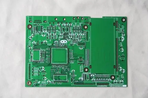
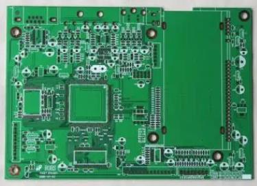
High quality PCB design
This article is a summary of some experience about PCB layout. The content in the article is mainly suitable for high-precision analog systems or low-frequency (<50MHz) digital systems.

1. Component layout
Reasonable component layout is the basic prerequisite for designing high-quality PCB diagrams. The requirements for component layout mainly include installation, force, heat, signal, and aesthetic requirements.
1.1. Installation
Refers to a series of basics proposed in order to smoothly install the circuit board into the chassis, shell, slot, etc., without space interference, short circuit and other accidents, and make the designated connector in the designated position on the chassis or shell under specific application occasions. Require. I won't repeat it here.
1.2. Force
The circuit board should be able to withstand various external forces and vibrations during installation and work. For this reason, the circuit board should have a reasonable shape, and the positions of the various holes (screw holes, special-shaped holes) on the board should be arranged reasonably. Generally, the distance between the hole and the edge of the board should be at least greater than the diameter of the hole. At the same time, it should be noted that the weak section of the plate caused by the special-shaped hole should also have sufficient bending strength. The connectors that directly "extend" from the device shell on the board must be reasonably fixed to ensure long-term reliability.
1.3. Heated
For high-power devices with severe heat generation, in addition to ensuring the heat dissipation conditions, they should also be placed in appropriate locations. Especially in sophisticated analog systems, special attention should be paid to the adverse effects of the temperature field generated by these devices on the fragile preamplifier circuit. Generally, the part with very large power should be made into a module separately, and certain thermal isolation measures should be taken between the signal processing circuit and the signal processing circuit.
1.4. Signal
Signal interference is an important factor to be considered in PCB layout design. Several basic aspects are: the weak signal circuit is separated or even isolated from the strong signal circuit; the AC part is separated from the DC part; the high frequency part is separated from the low frequency part; pay attention to the direction of the signal line; the layout of the ground line; proper shielding, filtering, etc. measure. These have been repeatedly emphasized in a large number of treatises, so I won't repeat them here.
1.5. Beautiful
It is not only necessary to consider the neat and orderly placement of components, but also the beautiful and smooth wiring. Because ordinary laymen sometimes emphasize the former more in order to one-sidedly evaluate the pros and cons of the circuit design, for the image of the product, the former should be given priority when the performance requirements are not harsh. However, in high-performance occasions, if you have to use a double-sided board, and the circuit board is also encapsulated in it, and it is usually invisible, the aesthetics of the wiring should be emphasized first. The next section will discuss the "aesthetics" of wiring in detail.
2. Wiring principle
The following is a detailed introduction to some uncommon anti-jamming measures in the literature. Taking into account that in practical applications, especially in the trial production of products, a large number of double panels are still used, the following content is mainly for double panels.
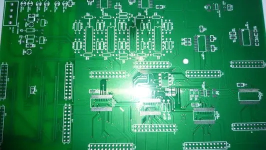
2.1. Wiring "Aesthetics"
Avoid right angles when turning, and try to use diagonal or arc transitions.
The wiring should be neat and orderly, arranged in a centralized manner, which can not only avoid the mutual interference of signals of different natures, but also facilitate inspection and modification. For digital systems, there is no need to worry about interference between signal lines (such as data lines, address lines) in the same camp, but control signals such as read, write, and clock should be used independently for protection by ground wires. stand up.
When laying a large area (discussed further below), try to keep a reasonable and equal distance between the ground wire (actually should be the ground "plane") and the signal wire, and try to be as close as possible to prevent short circuit and leakage.
For the weak current system, the ground wire and the power wire should be as close as possible.
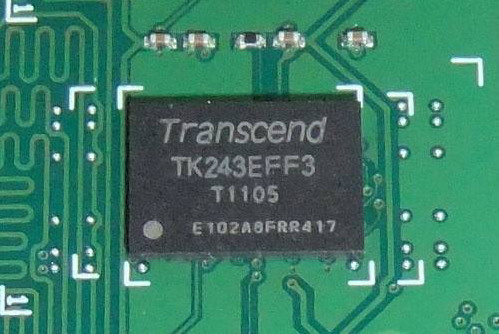
For systems using surface mount components, the signal lines should be routed to the front as much as possible.
2.2. Ground wire layout
There are many discussions on the importance and layout principles of the ground wire in the literature, but there is still a lack of detailed and accurate introduction about the ground wire arrangement in the actual PCB. My experience is that in order to improve the reliability of the system (not just to make an experimental prototype), the ground wire cannot be overemphasized, especially in weak signal processing. To this end, we must spare no effort to implement the principle of "large area paving".
When paving the ground, it must generally be a grid-like ground, unless the scattered ground is divided by other lines. The thermal performance and high-frequency conductivity of the grid-like ground are much better than the whole ground wire. In double-panel wiring, sometimes in order to route the signal line, the ground line has to be separated, which is extremely disadvantageous for keeping the ground resistance low enough. For this reason, a series of "smart" methods must be adopted to ensure the "smoothness" of the ground current. These techniques include:
A large number of surface mount components are used to save the space occupied by solder holes that should belong to the ground wire.
Make full use of the front space: In the case of a large number of surface mount components, try to make the signal line go to the top layer as much as possible, and give the bottom layer "selflessly" to the ground wire. This involves countless small tricks. My own book "PCB One of the tricks: "Swap Pins", there is a trick, and there are many similar spells, which will be written in the future.
Reasonably arrange the signal lines, and "give" important areas on the board, especially the "hinterland" (which is related to the communication of the entire board ground wire), to the ground wire. As long as it is carefully designed, this can still be achieved.
Coordination of the front and the back: Sometimes on one side of the board, the ground wire is really "nowhere". At this time, try to make the wiring on both sides coordinate with each other. At the corresponding position, leave a sufficient ground to lay the ground wire, and then pass through a sufficient number of vias with a reasonable location (considering that the vias have a large resistance), pass the signal line that will be crossed by the "bridge" The two sides of the Taiwan Strait, which are forced to divide but reluctantly, hope for reunification, are connected into a whole with sufficient conductivity.
The number of the dog jumping over the wall: When the huge ground wire is cut off by a small signal wire because I can't get out of the place, let the signal be wronged and use the jumper wire. Sometimes, I am unwilling to just pull a bare wire. This signal happens to pass through a resistor or other "long-legged" device. I can justifiably extend the pin of this device and make it serve as a jumper. It not only passes the signal, but also avoids the indecent name of the jumper wire:-(Of course, in most cases, I can always let such a signal pass through the appropriate place and avoid crossing the ground wire. The only thing needed is Observation and imagination.
The minimum principle: the path of the ground current must be reasonable, and the high current and the weak signal current must not go side by side. Sometimes, when choosing a reasonable path, a platoon of ground lines is worth an unreasonably configured army.
After, by the way, there is a famous saying: "You can trust your mother, but never trust your land". In the case of extremely weak signal processing (below microvolts), even if the ground potential is kept consistent by unscrupulous means, the ground potential difference at key points on the circuit must still exceed the amplitude of the processed signal, at least the same magnitude, even if the static potential is appropriate, The instantaneous potential difference may still be large. For such occasions, first of all, in principle, the operation of the circuit should be as independent of the ground potential as possible.
2.3. Power cord layout and power filtering
The general literature thinks that the power cord should be as thick as possible, which I can’t completely agree with. Only in the high-power (average power supply current may reach 1A within 1 second), it is necessary to ensure sufficient power line width (in my experience, each 1A current corresponding to 50mil can meet the needs of most occasions). If it is only to prevent signal interference, the width of the power line is not critical. Even, sometimes a thinner power cord is more advantageous! The quality of the power supply generally lies not in its absolute value, but in the fluctuation and superimposed interference of the power supply. The key to solving power interference is the filter capacitor! If your application does have demanding requirements on power quality, don't save money on filter capacitors! Pay attention to the following points when using filter capacitors:
The power input of the entire circuit should have "total" filtering measures, and various types of capacitors should be matched with each other, "the same must not be less", at least not bad. For digital systems, at least 100uF electrolysis + 10uF piece of tantalum + 0 .1uF patch + 1nF patch. Higher frequency (100kHz) 100uF electrolysis + 10uF tantalum + 0.47uF patch + 0.1uF patch. AC simulation system: For DC and low-frequency simulation systems: 1000uF | 1000uF electrolysis + 10uF tantalum + 1uF patch + 0.1uF patch.
Every important chip should have a "set" of filter capacitors. For digital systems, a 0.1uF patch is generally sufficient. Important or larger operating current chips should also be combined with a 10uF tantalum or 1uF patch, and high-frequency chips (CPU, crystal) should also be combined with 10nF |470pF or a 1nF. The capacitor should be as close as possible to the power pin of the chip and connected as directly as possible. The smaller the capacitor, the closer it should be.
For the chip filter capacitor, the section within (the filter capacitor to the chip power pin) should be as thick as possible, and it is better if multiple thin wires can be used side by side. With the filter capacitor providing a low (AC) impedance voltage source and suppressing AC coupling interference, the power line outside the capacitor pin (referring to the section from the main power supply to the filter capacitor) is not so important. The line width does not need to be too thick, at least There is no need to take up a lot of board area for this. Some analog systems also require the power input to adopt an RC filter network to further suppress interference, and a thinner power line sometimes just doubles as the resistance in the RC filter, which is beneficial.
For a system with a large operating temperature range, it should be noted that the performance of aluminum electrolytic capacitors will decrease or even lose their filtering effect at low temperatures. At this time, appropriate tantalum capacitors should be used instead. For example, replace 470uF aluminum with 100uF tantalum|1000uF aluminum, or replace 100uF aluminum with 22uF piece of tantalum.
Be careful not to keep the aluminum electrolytic capacitor too close to the high-power heating device.