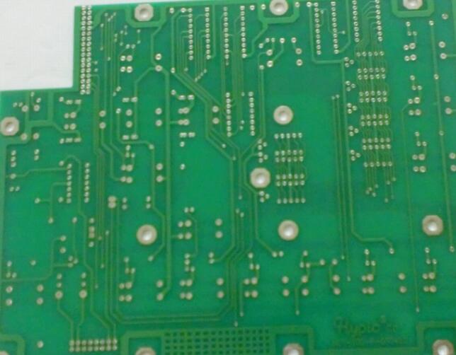
There are different numbers of output Gerber files for different PCB designs, especially for PCB designs of different layers. But generally speaking, there are seven types of board data that need to be output. These are:

(1)Routing (silk screen layer): If it is more than two layers, it will be divided into upper, lower or middle routing layer
(2) Silkscreen (silk screen layer): The multilayer board has upper and lower layers. If there is no silk screen on the bottom layer, it does not need to be printed;
(3) Plane (power supply, ground plane layer): only for multi-layer boards (output with negative film);
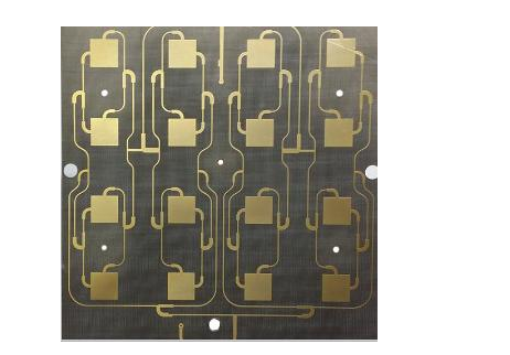
(4) Paste Mask (SMD patch layer);
Mainly for SMD components on PCB boards. If all Dip (through hole) components are placed on the board, there is no need to export Gerber files on this layer. Before attaching SMD components to the PCB board, solder paste must be applied to each SMD pad. The paste mask file must be used for the steel mesh used for tinning, and the film film can be processed.
The most important point of the Gerber output of the Paste Mask layer is to be clear, that is, this layer is mainly for SMD components. At the same time, compare this layer with the Solder Mask that will be introduced below to find out the different functions of the two, because from the film picture Look at these two film images are very similar.
(5) Solder Mask (main welding layer);
The main purpose is to ensure that the selected options (such as component foot pads and some special copper skins, etc.) are not covered by green oil on the PCB board and appear directly on the board in the form of copper skin. All objects that need to be soldered and pasted are not covered by green oil. It must be selected. Simply put, if you want an object to appear on the board in the form of bare copper in the design, you can select it in the output main solder layer.
For the main solder layer Gerber, the output option Pads must be selected, but the Pads (component foot pads) of the main solder layer are different from PastMask. It includes SMD and Dip pads, but PastMask only Contains SMD pads.
(6) NC Drill (NC drilling layer);
For the PCB board design with through holes, NC Drill output file is indispensable. Without this file, it is impossible to drill the PCB board.
(7) Drill Drawing (drilling reference layer);
The drilling reference chart is a data reference chart provided for drilling. Pay attention to the output of this layer. When setting the options, the objects with drilling holes generally need to be selected, because its output is mainly for drilling objects, such as Pads (pads) and Vias (vias).
Summarize:
When outputting film files, it is generally based on these seven categories. You only need to output according to this standard. How many film files need to be output depends on the designed PCB. For example, there is no bottom wiring and Plane for a single panel. (Plane) layer, but there may be two silk-screened Gerber files, etc., and there may be more than two wiring layers on the multilayer board. As long as the concept of the output Gerber file is clear, no matter how complicated the design is, it will never be separated from it.