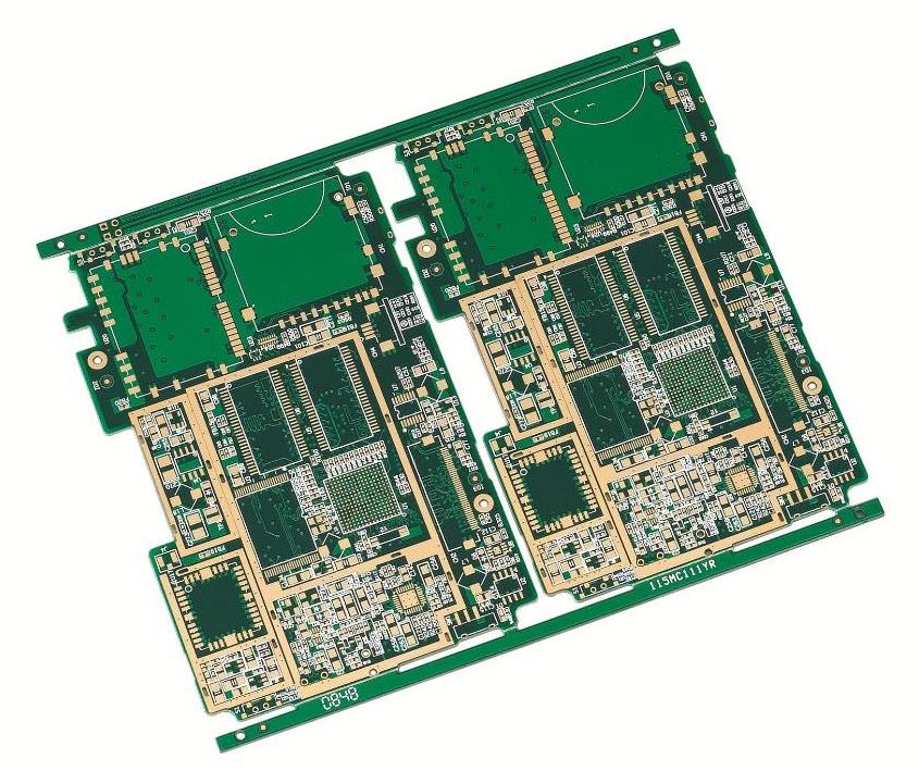
When producing BGA, fr4 pcb manufacturers are always prone to short circuit and empty welding, and they are all new materials. Generally speaking, there are not many cases of empty welding and short circuit in BGA welding at the same time, but it is not impossible. The edge is turned up, forming a curve similar to a smiling face, while the fr4 plate is too long, and the temperature difference between the upper and lower furnace temperatures of the reflow furnace is too large. Under the interaction of the two phases, the edge of the circuit board is bent down, resulting in the so-called crying face curve.

If the crying and laughing curves are seriously deformed, BGA short circuit and blank welding will be formed at the same time, but it is usually easy to occur when both occur at the same time. It can be clearly seen from the figure below that the smiling face of BGA and the crying face on the printed fr4 pcb strongly squeezed the solder ball of BGA, resulting in a short circuit between several machines. Generally speaking, it can be considered to reduce the heating slope of the reflow furnace, or preheat and bake BGA to eliminate its thermal stress, or require BGA manufacturers to use higher Tg and other methods to overcome. Other possible reasons for empty soldering of BGA include: oxidation of fr4 pcb solder pad or BGA solder ball. In addition, the printing of fr4 plate or BGA is not moisture-proof, which may cause similar problems. Solder paste expired. Insufficient solder paste printing. The temperature curve is poorly set, and the furnace temperature shall be measured at the empty welding position. In addition, when the temperature rises too fast, it is easy to cause the above problems of crying and smiling. fr4 pcb design problem. For example, Via-in-pad (through-hole on pad) will cause the reduction of solder paste, and in fact, it may also cause the hollow solder ball and blow up the solder ball. Pillow effect. This phenomenon often occurs when the above-mentioned BGA carrier plate or printed fr 4 pcb is deformed during reflow soldering. When the solder paste is melted, the BGA solder ball does not contact the solder paste. When it is cooled, the deformation of the BGA carrier plate and fr4 pcb decreases, and the solder ball falls back and contacts the solidified solder paste.
The general analysis methods of BGA empty welding are as follows:
1) Use a microscope to check the BGA tin balls on the periphery. Generally, you can only see the outermost row of tin balls. Even if you use fiber optical fiber, you can only check the outermost three rows, and the more inside, the less clear you can see.
2) X-ray inspection. It is easy to check the short circuit. Check the empty welding to see the power.
3) Red Dye PENETRATION. This is a destructive test, which must be used as a last resort. You can see the fracture and empty weld, but you need to be careful and experienced.
4) Slice. This method is also a destructive test, and it is more labor-intensive than the dye red test. It can be regarded as a special magnifying inspection of a certain area.
Both the back-welding of fr4 plate multilayer plate and the TCT test of multilayer plate will have a deterioration effect on the through-hole reliability. The main reason is, of course, that the CTE of the Z-axis of the plate is far more than the CTE of the copper wall. Therefore, reducing the CTE of the rubber 2Z-axis of the plate has become an urgent priority. However, simply increasing the ratio of filling agent Silica (for example, 20% of the resin weight ratio) will also lead to other adverse sequelae. Therefore, it is still to be further observed to fully promote Filler's mass production plate.
First of all, through the reflow with a peak temperature of 260 ℃ for 5-9 times. Secondly, the reliability of the through-hole shall not be inferior to the previous tin-lead welding. From the above tests, it can be seen that the Dicy hardened FR-4 has indeed failed to pass the test of the strong thermal stress of lead-free welding, while the Dicy hardened FR-4 has the opportunity to fill the gap. However, the manufacturing process of fr4 pcb is improved
The design of the lamination, the optimization of the assembler's reflow unit and reflow curve also play a very important role. According to the results of the long time TCT test of air to air, there is a close causal relationship between the long-term reliability of through-hole and its reflow peak temperature and reflow times. Too high reflow peak temperature and too many times will indeed damage the plate and through-hole, but the relationship between CTE/Z and TCT failure of the plate is not clear, and needs further clarification on the fr4 pcb.