1. Purpose: Used to guide the reflow soldering temperature curve test operation instructions.
2. Scope of application: suitable for SMT reflow soldering temperature test in SMT factory
3. Responsibilities: None
4. Homework content:
4.1 Set temperature parameter process limit:
4.1.1 Engineers formulate a reasonable temperature curve test range according to the solder paste model, special component specifications, special measurement locations, FPC manufacturing process and customer requirements, including: specific temperature rise zone, immersion (heat preservation) zone, reflow zone, and cooling zone Parameters and definitions
4.1.2 Preheating zone: usually refers to the area where the temperature rises from room temperature to about 150 degrees. In this temperature zone, the heating rate should not be too fast, generally not more than 3 degrees per second. In order to prevent the components from heating up too fast and causing the substrate to deform or crack the components.
4.1.3 Soaking (heat preservation) area: usually refers to the area from 110 degrees to 190 degrees. In this temperature zone, the flux further volatilizes and helps the substrate to clear oxides, and the substrate and components reach thermal equilibrium, preparing for high-temperature reflow. The general duration of this zone is 60~120 seconds.

4.1.4 Recirculation zone: usually refers to the temperature zone above 217 degrees. In this temperature zone, the solder paste melts quickly, quickly infiltrates the soldering surface, and forms a new alloy solder layer with the substrate PAD to achieve good soldering between the component and the PAD. The duration of this zone is generally set as: 45~90 seconds. The maximum temperature generally does not exceed 250 degrees (except for specific requirements).
4.1.5 Cooling zone: This zone quickly cools down the solder joints, solidifies the solder, refines the solder lattice, and improves the welding strength. The cooling rate in this area is generally set at about -3 to -1 degrees per second.
4.2 Production of temperature measuring board
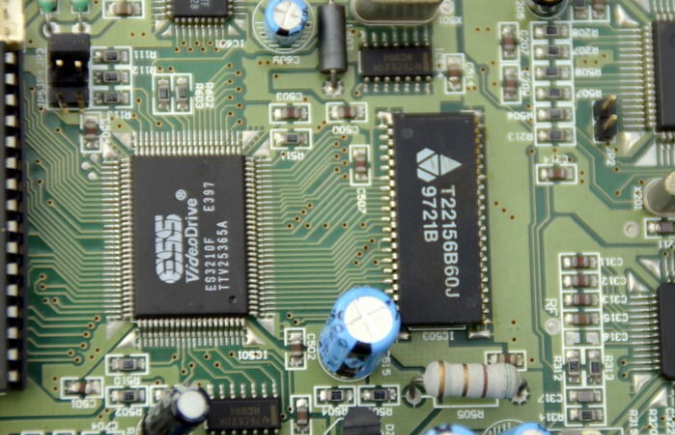
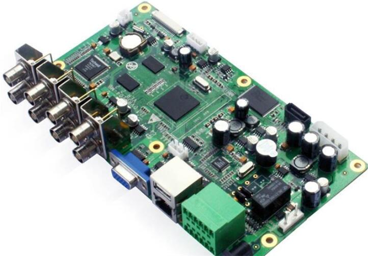
4.2.1 Use the sample board consistent with the production material number as the temperature measurement board. When making the temperature measurement board, in principle, the necessary representative temperature measurement components should be retained to ensure that the test measurement temperature is consistent with the actual production temperature.
4.2.2 If the temperature measurement board and the production material number cannot be consistent, after verification and approval by the PCBA engineer, the same type of temperature measurement board can be used for measurement.
4.2.3 The temperature measurement point should select the most representative area and components, such as the components with the largest and smallest heat absorption, and the priority of parts selection (such as Socket->Motor->large BGA -> small BGA->QFP or SOP ->Standard Chip) In addition, a temperature measurement zone between the two should also be selected.
4.2.4 Generally, there should be no less than 3 temperature measurement points on each board. At least 4 should be selected for BGA or large IC, and the components should be selected based on the principle that special representative components are the first choice.
4.2.5 Position distribution: Adopt the diagonal method of the whole board or the method of 4 corners 1 center point, which can cover the position distribution of the whole board.
4.2.6 The temperature measuring line should be fixed on the temperature measuring board with high temperature resistant yellow tape or red glue.
4.3 Test furnace temperature curve
4.3.1 According to the temperature process limits set by the engineer, the furnace temperature test technician pre-set the furnace temperature of each zone based on different reflow furnace structures to meet the temperature process requirements.
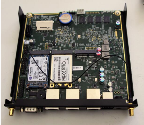
4.3.2 Insert the thermocouples on the temperature measuring board into the sockets of the tester one by one. Put on the protective cover, and note that the air line must be inserted into the first socket.
4.3.3 After the furnace temperature is set, the temperature measuring board can be used for testing after the green light of the reflow furnace lights up normally.
4.3.4 Put the temperature measuring board and the tester carefully on the conveyor belt or chain of the reflow soldering, and turn on the power of the tester and record the data switch. The boarding method should be the same as that of the produced board.
4.3.5 After the test is completed, take out the tester at the end of the board.
4.3.6 Read the temperature curve on the computer and check whether the curve is within a reasonable process range, otherwise the technician needs to continue to debug the temperature of each zone until the temperature curve that meets the process limit is measured.
4.4 Data collection
4.4.1 Open the computer reflow soldering temperature measurement program. And check whether the solder paste process is OK.
4.4.2 Input relevant information including furnace temperature, temperature zone, chain speed, test channel, etc.
Enter the parameter value of the reflow soldering test
4.4.3 Connect the thermometer according to the prompts and start reading data.
Connect thermometer to export data
4.4.4 Analyze the data according to the temperature curve requirements, and print out the temperature curve that meets the requirements for archiving.
4.4.5 Fill in the "Temperature Curve Confirmation Form", and post it on the reflow oven after ME and IPQC jointly confirm OK.
4.5 Inspection after furnace
Check the welding condition of the substrate after the furnace at this temperature setting, and confirm the reasonableness of the setting range and furnace temperature parameter setting according to the welding yield.
4.6 Test frequency
The temperature curve of reflow soldering is tested once a day by the technician. If the wire is changed, it should be done again, and the correct temperature curve should be printed out, and the corresponding "Temperature Curve Confirmation Form" should be filled in.
4.7 Notes:
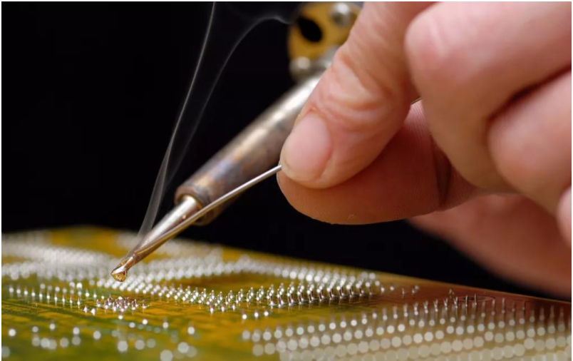
4.7.1 If the customer needs to measure the IC/QFP temperature, the thermocouple wire should be connected to the IC pin.
4.7.2 If the customer requires to measure the BGA temperature, drill a hole at the position of the BGA pad on the front of the test board until the back, and insert the thermocouple wire from the back of the test board to the solder joint of the BGA. At the same time, solder the entire BGA on the test board.
4.7.3 To measure the temperature of the hand-soldering component, the thermocouple wire should be passed through the PCB solder hole from the front, and the length of the extension of the test board is 1.5-2mm in order to contact the tin wave.
4.8 Health and safety: Pay attention to safety during the test to prevent high temperature burns.