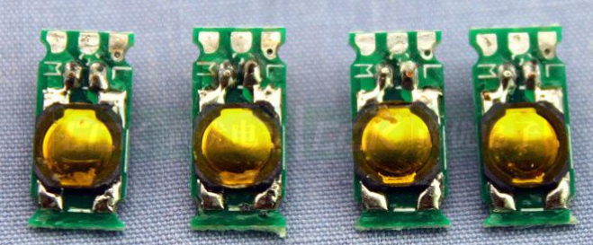
PCB reflow soldering is to use tin and lead alloy as the component of solder paste. The solder paste is heated and liquefied by non-touch heating methods such as infrared rays, hot air, etc. The wave soldering method can be used to solder components with pins and some externally adhered components, but it should be noted that these components must be fixed with epoxy resin before they are exposed to the molten tin furnace. The following online production methods are available for reference: reflow soldering, PCB double-sided reflow soldering, reflow/wave soldering, double-sided reflowing/wave soldering, double-sided reflowing/selective wave soldering, etc.
The Ruppert process provides process engineers with a method for soldering reflow components and plug-in components in one pass. Place a calculated amount of solder paste near each perforated pad. When the solder paste is melted, it will actively flow into the through hole, fill the hole and complete the solder joint. When using this method, the components must be able to withstand the high temperature during reflow.

Tool development files Development of PC board assembling tools requires detailed data such as CAD. The data used by Gerber file or IPC-D-350 to manufacture the board is also often used when compiling machine programs, opening and printing steel plates and manufacturing test fixtures. Although the compatibility of the programs used in each part is different, the fully active mechanical equipment generally has software that actively transforms or translates the CAD data into a recognizable format. Units that use data include programs for assembling machines, manufacturing of printed steel plates, manufacturing of vacuum fixtures, and testing fixtures, etc.
It is impractical to decide that the most powerful assembly provides the same assembly procedure for all products. Regarding the assembly of different PCB parts, different densities and clutter, at least two or more assembly processes will be used. As for the more difficult assembly of fine pitch components, different assembly methods are required to ensure power and yield.
When the complexity of the process increases, so does the cost. For example, before drawing the fine pitch component on one side or both sides, the drawing person must know the difficulty and cost of the process. The other is the mixed process. PC boards generally use a mixed process, that is, a perforated component is included on the board. In an automated production line, reflow soldering is the primary method for exterior adhesive components, while wave soldering is the primary method for pinned components. At this time, for components with pins, it is necessary to wait for the reflow components to be assembled before assembling them.
The consistency of the placement of the external adhesive components is not entirely necessary to describe the placement of all components as the same, but for the same type of components, the consistency will help improve the efficiency of assembly and inspection. For a messy board, components with pins generally have the same placement to save time. The reason is that the grab heads for placing the components are generally fixed in one direction, and it is necessary to rotate the board to change the placement position. As for the general surface adhesive components, because the gripper of the placement machine can rotate freely, there is no problem in this respect. But if you want to go through the wave soldering furnace, the components must be aligned in their orientation to reduce the time they are exposed to the tin flow.
Assembling the board can be appropriately simple or very messy, depending on the shape and density of the PCB components. A messy depiction can make a powerful production and reduce the difficulty, but if the depicter does not pay attention to the details of the process, it will become very difficult. The PCB assembly plan needs to be considered at the beginning of the drawing. Generally, as long as the orientation and placement of the components are adjusted, the mass production can be increased. If the PC board is small in size, has an irregular shape or has components very close to the edge of the board, you can think about the method of connecting the board for mass production.