How to quickly solve the problem of circuit board failure
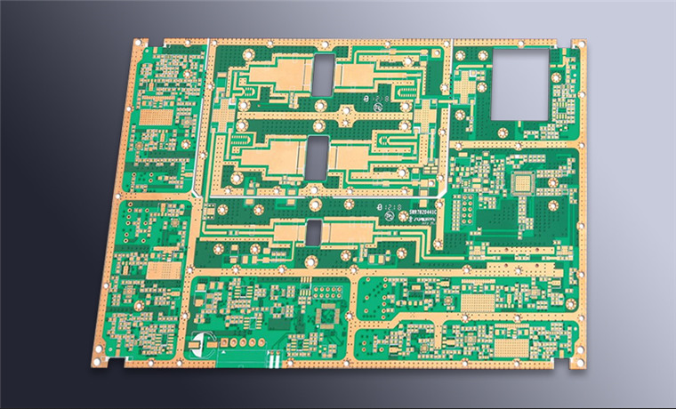
Circuit board production involves a series of complex and precise manufacturing processes. As PCB circuit boards become more integrated and more complex, the manufacturing process becomes more and more challenging for circuit board production personnel, and there is a possibility of defects and failures. Increased accordingly.
Regardless of the reason, for personal use or commercial applications, defects in circuit board manufacturing can cause serious adverse consequences. For example,circuit board failures in important medical equipment may be life-threatening, while problems with smartphones or automotive electronics can interfere with users activity.
What are the common defects of circuit boards/circuit boards?
The defects in the PCB circuit board include solder bridges or different solder joints between component pins, short circuits between copper wires, open circuits, component shifts, and so on. In most cases, manufacturers will conduct extensive testing before launching their products on the market. However, some defects may be overlooked, and the defects will only become obvious after the board is actually used by the user. In addition, due to the environment and other conditions beyond the control of the manufacturer, some defects may occur on site. In addition, some defects occur because they occur outside the scope of the manufacturer's controllable environment or other conditions.

Short circuit
The types of short circuits that occur in the PCB production stage are not the same, while other short circuits occur, during the process of soldering or reflow soldering, common short circuits include:
1. When the space or distance between copper traces is very small, a short circuit will occur;
2. Leads of components that are not trimmed will cause short circuits;
3. Floating in the air can lead to short thin wires, which will cause short circuits between copper traces.
Solder bridge
Component failure: A defective component usually shorts its input or output to power or ground.
open circuit
When the trace is broken, or when the solder is only on the pad and not on the component lead, an open circuit can occur. In this case, there is no adhesion or connection between the component and the PCB circuit board. Just like short circuits, these may also occur during the production process or during the welding process and other operations. Vibration or stretching of the circuit board, dropping them or other mechanical deformation factors will destroy the traces or solder joints. Similarly, chemical or moisture can cause solder or metal parts to wear, which can cause component leads to break.
Loose or misplaced electronic components
During the reflow soldering process, small parts may float on the molten solder and eventually leave the target solder joint. Possible reasons for the displacement or tilt include the vibration or bounce of the components on the soldered PCB board due to insufficient circuit board support, reflow oven settings, solder paste problems, and human error.
Welding problem
The following are some of the problems caused by poor welding practices:
Disturbed solder joints: The solder moves before solidification due to external disturbances. This is similar to a cold solder joint, but the reason is different. It can be corrected by reheating, and it is guaranteed that the solder joint will not be disturbed by the outside when it is cooled.
Cold welding: This situation occurs when the solder cannot be melted properly, resulting in rough surfaces and unreliable connections. Since excessive solder prevents complete melting, cold solder joints may also occur. The remedy is to reheat the joint and remove the excess solder.
Solder bridge: This happens when solder crosses and physically connects two leads together. These may form unexpected connections and short circuits, which may cause the components to burn out or burn out the traces when the current is too high.
Insufficient wetting of pads, pins, or leads.
Too much or too little solder.
Pads that are elevated due to overheating or rough soldering.
Fault location and repair technology
Once there are signs of a problem, the next step is to track and determine the location. This needs to follow a logical path until it is possible to identify the defect. Different ways to determine the location of the fault include visual inspection without powering the circuit board, and physical inspection using test equipment. Testing technology relies on high-end testing equipment or the use of basic tools, such as multimeters, on powered or unpowered boards.
Although it is easy to identify visible defects or problems on simple single-sided boards with larger traces, troubleshooting complex multi-layer boards is often a challenge. The degree of difficulty depends on the type of circuit board, number of layers, trace spacing, number of components, circuit board size and other factors.
Although more complex circuit boards usually require special test equipment, basic tools such as multimeters, thermal imaging cameras, magnifiers, and oscilloscopes can identify most problems.
The high-end test equipment combines a variety of measurement methods including micro-voltage and other non-contact current tracking technologies to accurately and quickly identify short circuits in the load and bare PCB. Some of these devices use current injection and field sensing to identify the exact location without powering the circuit board or removing components. However, the high cost may be beyond the reach of many designers.
Nordson Testing Equipment
Typical equipment includes automatic flight detection instruments, such as the double-sided robot tester Takaya 9600 and Acculogic FLS980. There are also automatic optical inspection (AOI) machines, such as Nordson YESTECHFX-942. AOI uses high-resolution cameras to inspect various defects, including shorts, open circuits, missing, incorrect or misaligned components.
Visual and physical inspection
Visual inspection can identify defects such as overlapping traces, short-circuited solder joints, signs of overheating of the circuit board, and burned components. But this is only within the reach of vision.
Some problems, especially when the circuit board is overheated and difficult to identify with the naked eye. In this case, a magnifying glass can help identify some short circuits, solder bridges, open circuits, cracks in solder joints and circuit board traces, component offsets, and so on.
In addition, the multimeter can determine whether there is a short circuit or open circuit in the copper traces on the board. Using the continuity test, the short-circuit resistance value will be very low, usually less than 5 ohms. Similarly, an open circuit will produce a very high resistance value.
Detect circuit board defects with a multimeter
When low resistance is detected between the pins of electronic components, the best way is to remove the components from the PCB circuit for special testing. If the resistance is still low, then this component is the culprit, otherwise further investigation is needed. Care should be taken when desoldering, so as not to damage the copper pads on the PCB or directly pull out the components to be tested from the PCB circuit board.
Visual inspection is only suitable for inspection of the appearance of the circuit board, and it may not be suitable for inspection of the inner layer of the circuit board. If there are no obvious defects in the appearance, you need to power on the circuit board and perform more detailed tests to detect whether the circuit board is normal.
Locate PCB short circuit problems
The above detection method has limitations, and it is because the detection is performed without powering on the circuit board. Only a limited number of problem points can be detected. In other words, it is easier to find the exact location of defects that are difficult to find, such as a short circuit on a powered-on circuit board. This involves using tools such as a voltmeter to measure the voltage drop on the copper trace, or using an infrared camera to identify heating problems.
Low voltage measurement
This technique involves controlling the amount of current passing through the short circuit and finding out where the current flows. Since the copper traces on the circuit board also have resistance, the voltages generated by different parts of the copper traces are also different. The amount of voltage depends on the length, width, and thickness of the copper traces. Because these factors cause different resistance values, the corresponding voltage values are also different.
It is very important to set a safe current useful for testing, but its value cannot exceed the wire or equipment safety threshold. A typical setting provides a supply voltage of 2 volts with a maximum current of approximately 100 mA. This will provide a total usable power of about 200mW, which is not enough to damage any parts except very sensitive parts. Sometimes, you can also use a low voltage with (such as 0.4 volts) current as high as 1 ampere or higher, but care should be taken to limit the current to a safe value that will not burn the copper traces.