About mixed circuit PCB material selection and wiring considerations
Question: In today's wireless communication equipment, the radio frequency part often adopts a miniaturized outdoor unit structure, while the radio frequency part, the intermediate frequency part of the outdoor unit, and the low frequency circuit part that monitors the outdoor unit are often deployed on the same PCB. Excuse me, what are the material requirements for such PCB wiring? How to prevent radio frequency, intermediate frequency and low frequency circuits from interfering with each other?
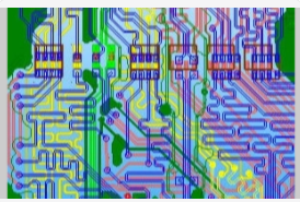
Answer: Hybrid circuit design is a big problem, and it is difficult to have a perfect solution. Generally, the radio frequency circuit is arranged and wired as an independent single board in the system, and there is even a special shielded cavity. Moreover, the radio frequency circuit is generally single-sided or double-sided, and the circuit is relatively simple, all of which are used to reduce the influence on the distribution parameters of the radio frequency circuit and improve the consistency of the radio frequency system. Compared with general FR4 materials, RF circuit boards tend to use high-Q substrates. This material has a relatively small dielectric constant, a small transmission line distributed capacitance, high impedance, and small signal transmission delay.
In hybrid circuit design, although radio frequency and digital circuits are built on the same PCB, they are generally divided into radio frequency circuit area and digital circuit area, and they are laid out and routed separately. Use grounding via tape and shielding box to shield between them.

Regarding input and output termination methods and rules
Question: In modern high-speed PCB design, in order to ensure the integrity of the signal, it is often necessary to terminate the input or output of the device. What are the termination methods? What factors determine the way of termination? What are the rules?
Answer: Terminal, also called matching. Generally, there are active end matching and terminal matching according to the matching position. The source terminal matching is generally resistance series matching, and the terminal matching is generally parallel matching. There are many ways, including resistance pull-up, resistance pull-down, Thevenin matching, AC matching, and Schottky diode matching. The matching method is generally determined by the BUFFER characteristics, topological conditions, level types and judgment methods, and the signal duty cycle, system power consumption, etc. should also be considered. The most critical aspect of the digital circuit is the timing issue. The purpose of adding matching is to improve the signal quality and obtain a determinable signal at the moment of decision. For level-valid signals, the signal quality is stable under the premise of ensuring the setup and hold time; for the valid signals, the signal change delay speed meets the requirements under the premise of ensuring the monotonicity of the signal delay.
What problems should be paid attention to when dealing with wiring density?
Question: When the size of the circuit board is fixed, if the design needs to accommodate more functions, it is often necessary to increase the trace density of the PCB, but this may increase the mutual interference of the traces, and at the same time, the impedance of the traces is too thin Can’t be lowered. What are the skills in high-speed (》100MHz) high-density PCB design?
Answer: When designing high-speed and high-density PCBs, crosstalk interference (crosstalk interference) really needs special attention, because it has a great impact on timing and signal integrity. Here are a few points for attention: 1. Control the continuity and matching of the characteristic impedance of the trace. 2. The size of the trace spacing. The commonly seen spacing is twice the line width. It is possible to know the influence of trace spacing on timing and signal integrity through simulation, and find the minimum tolerable spacing. The result of different chip signals may be different. 3. Choose the appropriate termination method. 4. Avoid two adjacent layers with the same wiring direction, even if the wiring overlaps up and down, because this kind of crosstalk is larger than that of adjacent wiring on the same layer. 5. Use blind/buried vias to increase the trace area. However, the manufacturing cost of the PCB board will increase. It is indeed difficult to achieve complete parallelism and equal length in actual implementation, but it is still necessary to do it as much as possible. In addition, differential termination and common mode termination can be reserved to alleviate the impact on timing and signal integrity.
About impedance matching in PCB design
Question: In order to prevent reflection, impedance matching must be considered in high-speed PCB design. However, because the PCB processing technology limits the impedance continuity and simulation cannot be simulated, how to consider this issue in the design of the schematic? In addition, regarding the IBIS model, I wonder where a more accurate IBIS model library can be provided. Most of the libraries we downloaded from the Internet are not very accurate, which greatly affects the reference of the simulation.
Answer: When designing high-speed PCB circuits, impedance matching is one of the design elements. The impedance value has an absolute relationship with the wiring method, such as walking on the surface layer (microstrip) or inner layer (stripline/double stripline), distance from the reference layer (power layer or ground layer), wiring width, PCB material, etc. Both will affect the characteristic impedance value of the trace. That is to say, the impedance value can only be determined after wiring. Generally, simulation software cannot take into account some wiring conditions with discontinuous impedance due to the limitation of the circuit model or the mathematical algorithm used. At this time, only some terminators (termination), such as series resistance, can be reserved on the schematic diagram. Alleviate the effect of discontinuity in trace impedance. The real solution to the problem is to try to avoid impedance discontinuities when wiring. The accuracy of the IBIS model directly affects the simulation results. Basically, IBIS can be regarded as the electrical characteristic data of the equivalent circuit of the actual chip I/O buffer, which can generally be obtained by conversion from the SPICE model (measurement can also be used, but there are more restrictions), and the SPICE data and chip manufacturing have absolute Therefore, the SPICE data of the same device provided by different chip manufacturers is different, and the data in the converted IBIS model will also vary accordingly. In other words, if manufacturers A’s devices are used, only they have the ability to provide accurate model data for their devices, because no one else knows better than them what process their devices are made of. If the IBIS provided by the manufacturer is inaccurate, the fundamental solution can only be to continuously ask the manufacturer to improve.
About EMC and EMI issues in high-speed PCB design
Q: When designing high-speed PCBs, the software we use is only to check the EMC and EMI rules that have been set, but from which aspects should the designer consider the EMC and EMI rules? How to set up rules?
Answer: In general EMI/EMC design, both radiated and conducted aspects need to be considered. The former belongs to the higher frequency part (<30MHz) and the latter is the lower frequency part (<30MHz). So you can't just pay attention to the high frequency and ignore the low frequency part. A good EMI/EMC design must take into account the location of the device, PCB stack arrangement, important connection method, device selection, etc. at the beginning of the layout. If there is no better arrangement beforehand, it will be resolved afterwards. It will do twice the result with half the effort and increase the cost. For example, the location of the clock generator should not be as close as possible to the external connector. High-speed signals should go to the inner layer as much as possible. Pay attention to the characteristic impedance matching and the continuity of the reference layer to reduce reflections. The slew rate of the signal pushed by the device should be as small as possible to reduce the height. Frequency components, when choosing decoupling/bypass capacitors, pay attention to whether the frequency response meets the requirements to reduce noise on the power plane. In addition, pay attention to the return path of the high-frequency signal current to make the loop area as small as possible (that is, the loop impedance as small as possible) to reduce radiation. The ground can also be divided to control the range of high-frequency noise. Finally, properly select the chassis ground between the PCB and the housing.