Before putting into production, you can use the impedance calculator to determine the characteristic impedance of the flexible circuit (. The manufacturer of the flexible circuit can help you complete the calculation, or you can buy or download the impedance calculator. Some factors will affect the characteristics of the flexible PCB Impedance, the main factors include:
The dielectric constant of the insulating material used to construct the circuit
The width of the trace that carries the signal
The distance between the signal trace and the reference plane layer
The thickness of the trace that carries the signal
The distance between signal traces in differential impedance applications
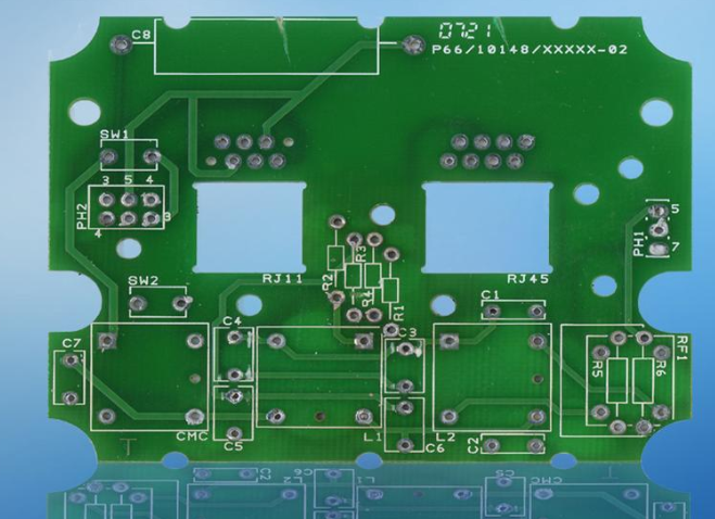
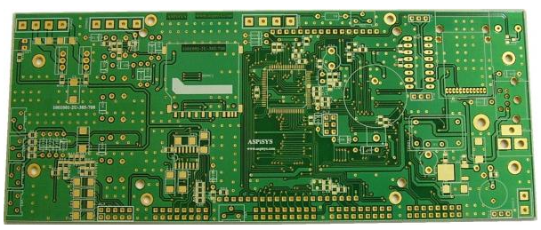
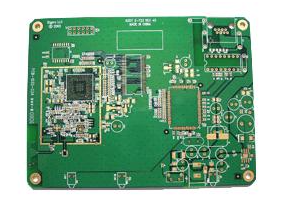
Standard double-layer circuit junction
The most common impedance requirements are 50 ohms to 75 ohms (single-ended) or 100 ohms to 110 ohms for differential signals. If you want to achieve this impedance value in a flexible circuit, you need to use a thicker insulating material than usual, resulting in a thicker and thicker circuit as a whole.
: The thickness of the controlled impedance part of the double-layer structure drawing with higher impedance requirements is increased, so it is flexible
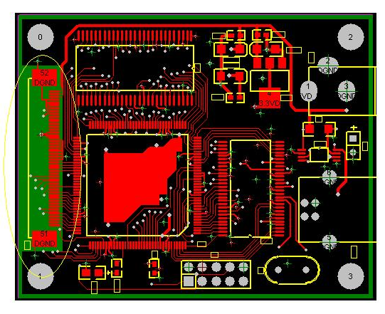
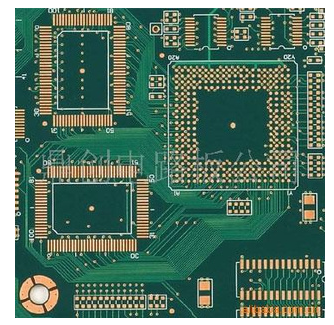
Plane layer and shielding layer
The reference plane layer and the external shielding layer play an important role in impedance control and signal integrity. Manufacturers can add plane layers with the following materials:
Additional etched copper layer
Screen printing conductive epoxy or conductive ink
Laminated conductive film
For internal planes that need to be connected through plated holes, a copper plane layer is required as a standard plane layer. The copper plane layer can make the flexible circuit better maintain its preformed shape, while the silk-screened conductive epoxy or conductive ink and laminated conductive film can enhance the flexibility of the flexible circuit.
Reinforced board

A wise approach is to use mechanical reinforcement plates to harden the SMT parts, connectors and other terminal areas on the flexible circuit. Flexible circuit manufacturers can add reinforced boards of any thickness made of epoxy glass laminate (FR-4) or polyimide film. In SMT applications, a reinforcement board should be added on the opposite side of the SMT components. In through-hole connectors and other through-hole applications, reinforcement plates should be added on the same side of the connector or through-hole components. Adding a reinforcement board in the connector area requires small holes that match the space occupied by the connector. The small hole in the reinforcement board should be at least 0.015" larger than the diameter of the clearance hole on the circuit.
Thermally isolated disk
A thermal isolation pad should be used on each pad surrounded by a large amount of copper. A large area of copper will dissipate heat from the non-thermally isolated disk, making it difficult to complete the soldering.
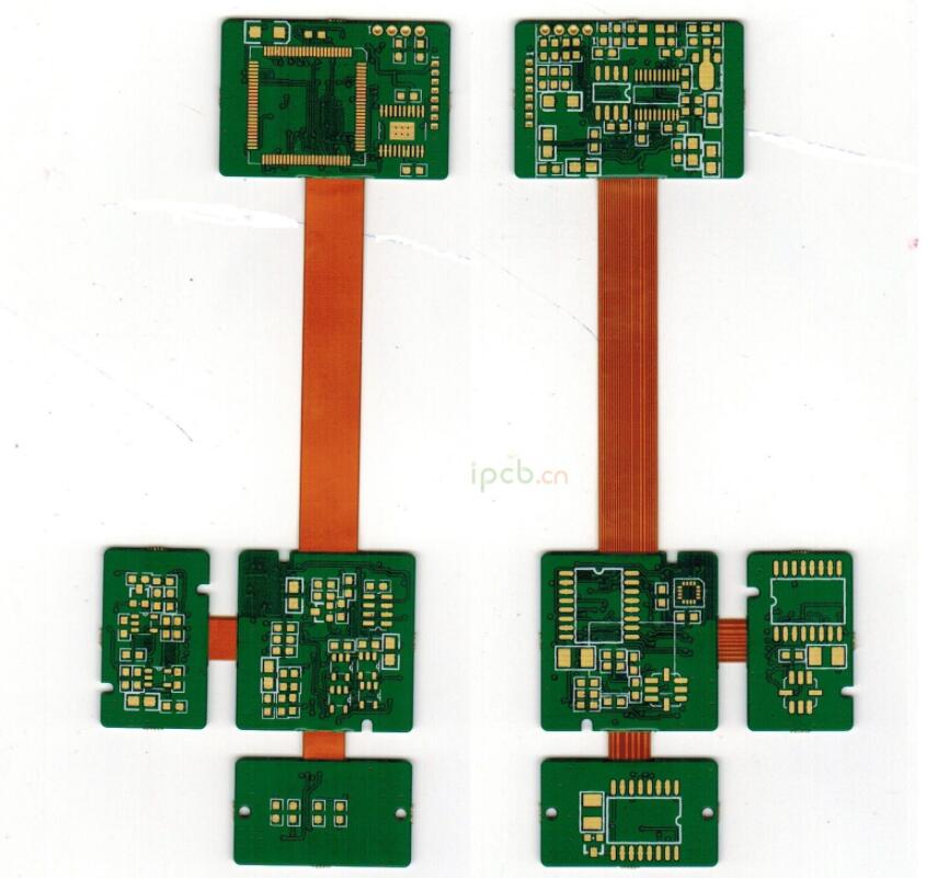
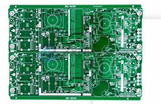
Rigid-flex circuit design guide
In view of the fact that the rigid-flex circuit is a hybrid circuit that combines a rigid PCB and a flexible PCB, there are special guidelines for this type of structure.
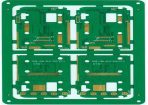
Typical Rigid-Flex Circuit
On rigid-flex circuits, make sure that all plated holes are in the rigid area (plated holes should not appear in the flexible area);
Clarify the use of non-sticky flexible materials, and whether the design of the rigid-flex combination uses a "cut-back" covering structure or a "bikini-like" covering structure. Acrylic adhesive is the only Achilles heel of plated holes on rigid-flex circuits. Avoiding the use of acrylic adhesives in the area of plated holes can greatly increase the reliability of plated holes;
The rigid areas connected by the flexible circuit should be at least 0.375" apart, preferably 0.5" or more apart;
Use "unbonded" structure to increase flexibility. When using an unbonded structure on a controlled impedance circuit, make sure that the signal layer and the reference plane layer have been bonded to each other. When the circuit is bent, the unbonded area will bend. If the signal layer and the reference layer are not bonded together, there will be impedance mismatch; after specifying the carrier board or "tray" used for component installation, Contact the manufacturer to ensure that the carrier board can effectively fit their processing panels, otherwise it will lead to a sharp increase in costs.
Factors that determine cost
All designers are looking for suitable methods to reduce costs without affecting performance. IPC research shows that decisions made by PCB designers will have an impact on 75% of circuit costs. It is very important for flexible circuit designers to know which functions can add value and which functions will only increase cost. Designers should never sacrifice reliability to save costs. At the same time, many specified flexible circuits are not necessary, and will only increase cost without adding additional value. The following characteristics are the main driving factors leading to the increase in circuit cost.
The number of circuit board layers: The increase in the number of layers will also lead to rising costs. The increase in the number of layers means the use of more materials and processing time. Flexible or rigid-flex circuits with a large number of processed layers may encounter very big technical challenges, resulting in a decrease in yield
Circuit size and shape: Most flexible circuits are made into a jigsaw form. The larger the area that the circuit occupies on the puzzle board, the higher the cost. There are some examples that show that even a slight modification to the circuit shape can save a lot of money. The slight change in the shape of the flexible circuit can also make the flexible circuit nesting on the puzzle board more reasonable, so that it is possible to add two more circuits on each puzzle board.
Circuit type (ie, comparison of category 3 and category 4): Rigid-flex circuits are usually more expensive than multilayer flexible circuits with reinforced boards. Check your design to determine whether the application requires a rigid-flex circuit structure, or it is sufficient to use a multi-layer PCB with a reinforced board. If necessary, you can call to consult the flexible PCB manufacturer
Circuit level (that is, the comparison of level 3 and level 2): The level 3 circuit requires additional testing, inspection and specific structural requirements, so the cost will be higher. Review the requirements of the application to determine which level of flex circuit you want to use
The dimensions used in the drawings are too large or too strict: remember that you are buying a flexible circuit, not a machined part. The material used to make the flexible circuit has a looser tolerance than the rigid PCB material, which is also allowed. Every size added to the drawing needs to be verified, so you have to ask yourself: "Will this size bring additional value or just add cost?" All non-critical dimensions on the flexible circuit drawing should be designated as references
Different number of layers in the area of plated holes: all areas with plated holes should have the same number of layers and structure
A variety of surface coatings: Although a variety of different surface coatings can be used, usually this approach requires a series of manual masking operations, so it will also increase the cost
Features: Because of the dimensional instability of the flexible PCB material itself, small circuit features (ie via pads) may cause processing difficulties and reduce yield. It is proved by examples that adding a layer with larger features is more cost-effective than a design with smaller features.