Common PCB circuit diagrams mainly include four types: schematic diagrams, block diagrams, assembly diagrams and printed board diagrams.
(1) Schematic diagram, also called "electrical schematic diagram". This kind of diagram, because it directly embodies the structure and working principle of the electronic circuit, is generally used in the design and analysis of the circuit. When analyzing the circuit, by identifying the various circuit component symbols drawn on the drawing and the connection between them, you can understand the actual working principle of the circuit. The schematic diagram is a tool used to reflect the working principle of the electronic circuit. .
(2) Block diagram (block diagram). A block diagram is a circuit diagram that uses blocks and connections to show the working principle and composition of the circuit. Fundamentally speaking,

this is also a kind of schematic diagram, but in this kind of drawing, there are almost no other symbols except for boxes and lines. The main difference between it and the above schematic diagram is that all the components of the circuit and their connection methods are drawn in detail on the schematic diagram, while the block diagram simply divides the circuit into several parts according to the function, and depicts each part. To form a box, add a simple text description in the box, and use a line between the boxes (sometimes use a line with arrows) to illustrate the relationship between the boxes. Therefore, the block diagram can only be used to reflect the general working principle of the circuit, and the schematic diagram can be used as a basis for collecting components and making circuits in addition to showing the working principle of the circuit in detail.
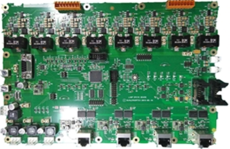
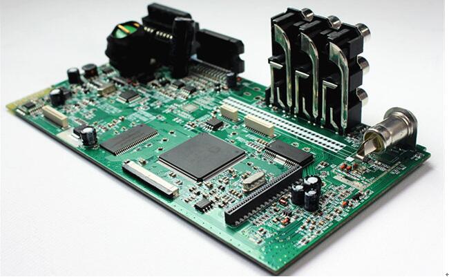
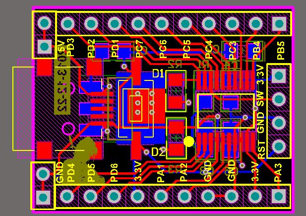
(Three), assembly drawing. It is a kind of drawing used for circuit assembly, and the symbols on the drawing are often the physical appearance drawings of the circuit components. As long as we follow the picture on the picture and connect some circuit components in the same way, we can complete the circuit assembly. This kind of circuit diagram is generally for beginners to use. The assembly drawings are different according to the different assembly templates. In most cases where electronic products are used, the PCB circuit boards described below are used, so printed board drawings are the main form of assembly drawings. When learning electronic knowledge, in order to be able to get in touch with electronic technology earlier, we chose the screw hole plate as the basic installation template, so the installation drawing becomes another mode.
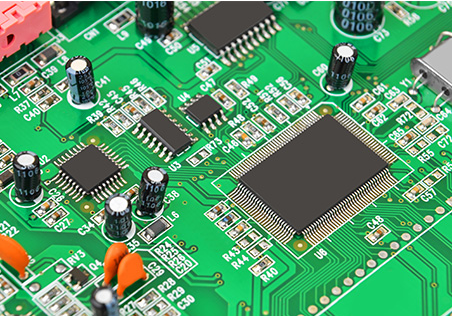
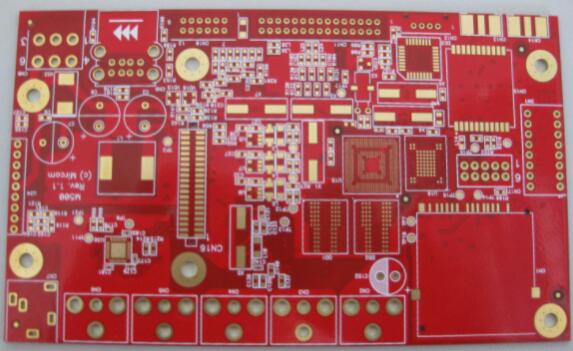
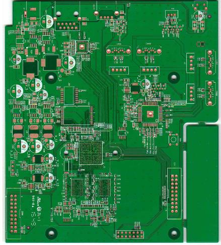
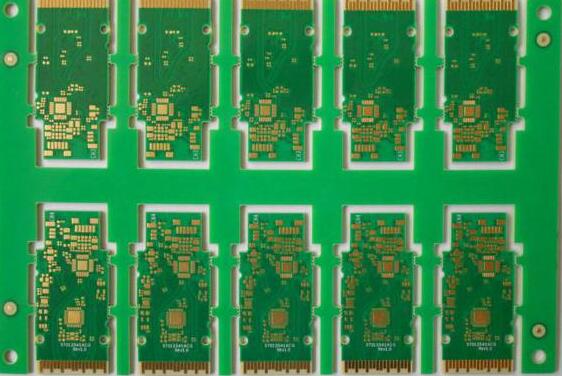
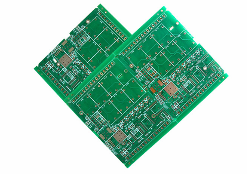
(Four), printed board map. The full name of the printed board diagram is "printed circuit board diagram" or "printed circuit board diagram", which is actually the same type of circuit diagram as the assembly diagram, and is used for assembling the actual circuit. The printed circuit board is covered with a layer of metal foil on an insulating board, and then the metal foil that is not needed by the circuit is corroded. The remaining part of the metal foil is used as the connection line between the circuit components, and then the components in the circuit The device is mounted on this insulating board, and the remaining metal foil on the board is used as a conductive connection between the components to complete the circuit connection. Because the metal covered on one or both sides of this circuit board is copper, the printed circuit board is also called "copper clad laminate."
The component distribution of the printed board diagram is often quite different from the schematic diagram. This is mainly because, in the design of the printed circuit board, the main consideration is whether the distribution and connection of all components are reasonable. It is necessary to consider many factors such as component volume, heat dissipation, anti-interference, anti-coupling, etc., and the printed circuit board designed by combining these factors From the outside, it is difficult to be completely consistent with the schematic; in fact, it can better realize the function of the circuit. With the development of science and technology, the production technology of printed circuit boards has been greatly developed; in addition to single-sided PCB boards and double-sided PCB boards, there are also multi-sided PCB boards, which have been widely used in daily life, industrial production, and national defense construction., Aerospace industry and many other fields. In the four forms of circuit diagrams introduced above, the electrical schematic diagram is the most commonly used and the most important. If you can understand the schematic diagram, you can basically master the principle of the circuit. Draw block diagrams, design assembly diagrams, and printed board diagrams. It's easy. It is also very convenient to master the schematic diagram to repair and design electrical appliances. Therefore, the key is to master the schematic diagram.