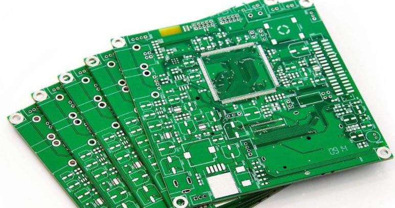
The following is an introduction to the image segmentation of PCB printed circuit boards:
1 Frontier
Threshold segmentation is a key step in image preprocessing. The essence is to determine a threshold for each pixel. According to the threshold, it is determined whether the current pixel is foreground or background. At present, there are a large number of threshold processing methods, such as global threshold and localization. Domain threshold is the simplest segmentation method, while the latter divides the entire image into many sub-images, and each image uses a different threshold for segmentation.
This paper analyzes the algorithm and proposes an improved adaptive threshold selection method based on this. Practice has proved that this method is simple, small in calculation, fast, statistically accurate, and can obtain the threshold of the image in time, and PCB image segmentation The effect is very good. After the image is segmented, the target graphics are guaranteed to be intact. After the image is enhanced, the open circuit and short circuit are made clearer and more prominent, making full preparations for the subsequent image processing.
2 Algorithm theory
Adaptive threshold segmentation algorithm:
(1) Divide the image into 4 sub-images;
(2) Calculate the mean value of each character image;

(3) Set the threshold value according to the mean value, and the threshold value is only applied to the corresponding sub-image;
(4) According to the threshold, each sub-block is divided.
In this algorithm, the average value is used as the threshold of the sub-block.
The gray distribution characteristics of printed circuit boards, which have the following characteristics:
(1) There are obvious background peaks and target peaks;
(2) The two peaks are far apart, and the gray values between them are basically the same, with no obvious troughs;
(3) The gray level changes of the background pixel point and the target pixel point are continuous, and the gray level of the target boundary is gradual, not abrupt.
Practice has proved that the algorithm is not suitable for printed circuit boards, and the segmentation effect is not very good, because the average gray level is not necessarily the trough of the histogram, and there is a large part of the flat area in the PCB histogram, even 0 gray In order to accurately segment the PCB image, it is necessary to find another effective method. Note that the average gray value point is between the two peak values (ie, the average gray value). The value is between the background gray value and the target gray value) and is close to the trough, so consider finding the minimum point in its area. In order to segment the target image of the PCB, the target peak of the histogram can be determined first, and then the minimum value point can be determined, and then the background peak can be found. The minimum value point is used as the segmentation threshold, and a gray scale is selected near the target peak and the background peak. The degree values are respectively used as the thresholds for open circuit and short circuit enhancement. In the PCB image, sometimes the target is sparse, but sometimes the target is dense. Finding the maximum point of the entire histogram is relatively simple, but how to determine whether this peak is the background peak or the target peak becomes the key to the problem.
For a general PCB image, the target (copper wire) is represented by a high gray scale, and the background is represented by a low gray scale. A feasible threshold search method is discussed below.
(1) Find the gray value corresponding to the largest peak. Find the maximum value of f(H) in the full gray interval [0, 255], and the corresponding value is H;
(2) Calculate the average gray level of the image:
(3) Determine whether it is a background peak or a target peak:
If the minimum value point is selected, the minimum value is found in the 30 neighborhood of the average point, and the corresponding value is Hmin.
Note: The size of the neighborhood can be selected according to the actual situation.
The second peak point determined by (5):
If only the background peak Hb is found in (3), then find the minimum value of f(H) in the gray interval [Hmin, 255), and the corresponding value is the target peak point Hf;
If the target peak value Hf is found in (3), then find the minimum value of f(H) in the gray interval [0, Hmin], and the corresponding value is the background peak point Hb;
(6) Use Hmin as the threshold to perform image segmentation;
Find a gray level (generally Hb+10) near the right side of the background peak Hb, and perform short-circuit enhancement;
Find a gray level (generally Hf-10) near the left side of the target peak Hf for open-circuit enhancement.
Note: This algorithm is especially suitable for continuous images of histograms. For discontinuous histograms, you can first perform adjacent interpolation and convert the histograms into continuous graphs. Then the above method can be used to determine the threshold.
3 Experimental results
When there is noise in the PCB image, two methods are usually adopted:
(1) Filter first and then binarize, so that the original PCB image will lose a lot of edge detail information, making the statistical results not accurate enough;
(2) No processing, but this will cause a lot of small noises in the image, and the statistical results are also not accurate enough.
In order to ensure the accuracy of the statistical results, neither should some edges of the image be lost and the line width reduced due to the influence of filtering, and those noise points should not be mistakenly regarded as lines for statistics. You can use binarization first and then remove them. Noise method.
In this experiment, the PCB image obtained from the camera is relatively clear and has very little noise, so it is processed directly.
The experimental results show that this method is a practical method, fast and simple.