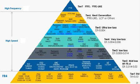
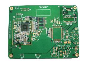
The following is an introduction to the safety distance and related safety requirements of the PCB specification system:
The safety distance includes insulation penetration distance, electrical clearance (spatial distance) and creepage distance (surface distance)
1. Creepage distance: the shortest distance between two adjacent conductors or one conductor and the surface of the adjacent motor casing measured along the insulating surface.
2. Electric clearance: the shortest distance measured along the air between two adjacent conductors or a conductor and the surface of the adjacent motor casing.
Determination of electrical clearance:
According to the measured working voltage and insulation level, the distance can be determined
For the requirements of the electrical gap size of the primary side circuit, see Table 1 and Table 2
See Table 3 for the clearance size requirements of the secondary side circuit
But usually: primary side AC part: L-N≥2.5mm before the fuse, L.N
PE (Earth) ≥ 2.5mm, after the fuse is not required, but keep a certain distance as much as possible to avoid short-circuit damage to the power supply.
Primary side AC to DC part ≥2.0mm
Primary side DC ground to earth ≥2.5mm

(Floating ground on the primary side to the earth)
The primary side part to the secondary side part ≥4.0mm, the components that are connected between the primary and secondary sides
The electric gap of the secondary side part is ≥0.5mm
The secondary side ground to the ground ≥1.0mm is enough
Note: Before deciding whether to meet the requirements, the internal parts should be applied with a force of 10N, and the outer shell should be applied with a force of 30N to reduce the distance, so that the space distance still meets the requirements in the worst case.
Determination of creepage distance:
According to the working voltage and insulation level
But usually: (1), primary side AC part: L-N≥2.5mm before the fuse, L.N
The earth ≥2.5mm, there is no requirement after the fuse, but try to keep a certain distance to avoid short-circuit damage to the power supply.
(2), the primary side AC to DC part ≥2.0mm
(3), primary side direct current ground to ground≥4.0mm, such as primary side ground to ground
(4), the primary side to the secondary side ≥6.4mm, such as optocoupler, Y capacitor and other components of the foot spacing of ≤6.4mm should be slotted.
(5) ≥0.5mm between the secondary side parts is enough
(6), the secondary side ground to the ground ≥ 2.0mm or more
(7) Between the two stages of the transformer ≥8.0mm
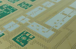
3. There are some points to note about PCB wiring process:
PCB components such as capacitors must be mounted flat without dispensing.
For example, the distance between two conductors can be shortened by applying a force of 10N. When the distance is less than the safety distance requirement, glue can be used to fix this part to ensure its electrical clearance.
When laying PVC film in some shell equipment, pay attention to ensuring the safety distance (pay attention to the processing technology)
Be careful not to make any foreign objects such as glue wires on the PCB board.
When processing parts, it should not cause insulation damage.
4. Insulation penetration distance:
According to the working voltage and insulation application, the following regulations should be met:
--The working voltage does not exceed 50V (71V AC peak value or DC value), and there is no thickness requirement;
--The minimum thickness of additional insulation should be 0.4mm;
--When the reinforced insulation does not withstand any mechanical stress that may cause deformation or performance degradation of the insulating material under normal temperature, the minimum thickness of the reinforced insulation should be 0.4mm.
If the insulation provided is used in the protective enclosure of the equipment and will not be bumped or scratched during maintenance by the operator, and falls under any of the following conditions, the above requirements do not apply to thin-layer insulation materials regardless of their thickness ;
-For supplementary insulation, use at least two layers of materials, each of which can pass the electrical strength test for supplementary insulation; or:
--Additional insulation composed of three layers of materials, of which any combination of two layers of materials can pass the electrical strength test of the additional insulation; or:
--For reinforced insulation, use at least two layers of materials, and each layer of PCB material can pass the electrical strength test for reinforced insulation; or:
--Reinforced insulation composed of three layers of insulating materials, of which any combination of two layers of PCB materials can pass the electrical strength test of the reinforced insulation.