90% of PCB design is in device layout and 10% is in wiring.
PCB design is both a technology and an art, but it needs to be carried out under constraints. The best PCB design starts with extraordinary device layout. In this article, Banermei will share with you some tips related to PCB component layout.
General requirements for device layout
1. The polar or directional THD devices have the same direction in the layout and are arranged neatly.
2. The recommended device layout direction is 0°, 90°.
3. Except for special needs such as interface devices, the body of other devices should not exceed the edge of the PCB to meet the requirement that the edge of the pin pad (or the device body) is ≥ 5mm from the transmitting edge.
4. The SMD that needs to install the radiator should pay attention to the installation position of the radiator, and the layout requires sufficient space to ensure that it does not collide with other devices.

5. Metal parts with different properties (such as potential difference, different power-ground properties, etc.) (such as radiators, shielding covers, etc.) or metal shell components should not touch each other.
6. The requirements of the device height and the handle bar meet the structure.
Tips for PCB device layout
1. Find out the physical limitations of the circuit board
Before placing the components, you first need to know exactly the mounting holes of the circuit board, the location of the edge connectors, and the mechanical size restrictions of the circuit board. Because these factors will affect the size and shape of your circuit board.
2. Leave the integrated chip blank
Nowadays, there are more and more chip pins and more and more dense. If the integrated chips are too close together, it is very likely that they cannot be easily routed out of their leads, and it is often more difficult to route them later. Therefore, when arranging any components, it is necessary to leave a distance of at least 350 mils between them as much as possible. For chips with more pins, more space is required.
3. The direction of the same device is the same
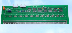
This is mainly to facilitate the later assembly, inspection and testing of the circuit board, especially for surface-packaged devices during the wave soldering process, the circuit board passes through the melting solder wave crest at a constant speed. The evenly placed devices have a uniform heating process, which can ensure high solder joint consistency.
▲ An example of uniform placement of components, the same orientation of the components is suitable for uniform wave soldering process
4. Reduce lead crossing
By changing the position and direction of the device, the lead crossing between the devices is minimized, which can save a lot of energy for the subsequent wiring.
5. Avoid conflicts between devices
Absolutely avoid overlapping and sharing the pads of the device for wiring in a small circuit board, or overlapping the edges of the device. It is best to maintain a distance of 40mil (1mm) between all devices. The most important reason for this is to avoid short-circuit faults between the pads in the subsequent circuit fabrication process.
6. Place the devices on the same side as much as possible
If you are designing a two-layer circuit board, the most common suggestion is to place the components on the same side. why? This is because: under normal circumstances, the components on the circuit board are completed by an automatic component placement machine, and the components are only on one side, and the PCB production process only needs to be done once. Otherwise, two device placements are required.