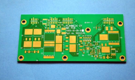
There are usually two types of high-speed PCB design rules: physical rules and electrical rules. The so-called physical rules refer to certain design rules specified by the design engineer based on physical dimensions, such as a line width of 4Mi1, a line-to-line spacing of 4Mi1, and a parallel trace length of 4Mi1. Electrical rules refer to design rules related to electrical characteristics or electrical performance. For example, the wiring delay is controlled between Ins and 2ns, the total amount of crosstalk on a PCB line is less than 70mV, and so on.

With a clear definition of physical rules and electrical rules, high-speed routers can be further discussed. At present, high-speed routers on the market based on physical rules (driven by physical rules) include AutoActive RE routers, CCT routers, B1azeRouter routers and Router Editor routers. In fact, these routers are all automatic routers driven by physical rules. That is to say, these routers can only automatically meet the physical size requirements specified by the design engineer, and cannot be directly affected by the physical size requirements of the high-speed electrical, and cannot be directly driven by the high-speed electrical rules.
High-speed routers directly driven by electrical rules are very important to ensure the integrity of high-speed design signals. Design engineers are always the first to obtain electrical rules and design specifications are also electrical rules. In other words, our design must ultimately meet electrical rules and It is not a physical rule, but the final physical design implementation meets the electrical rule requirements of the design is the most essential. Physical rules are just a conversion of electrical rules made by component manufacturers or design engineers themselves. We always expect this conversion to be equivalent and one-to-one correspondence. This is not the case in reality.
Take the use of LVDS chips to complete high-speed (up to 777.76Mbps) and long-distance (up to loom) data transmission as an example. Since the signal swing of LVDS technology is 3500, the usual design specifications always require the total signal line The crosstalk value should be less than or equal to 20% of the signal swing, that is, the total amount of crosstalk is 350mV X20%=700. This is the electrical rule. The percentage of 20% depends on the noise tolerance of LVDS, which can be obtained from the reference manual .
For IS_Synthesizer, the design engineer only needs to specify the crosstalk value of the LVDS signal line, and the wiring can automatically adjust and refine to ensure that the electrical performance requirements are met. During the wiring process, the surrounding signal lines will be automatically considered. The influence of LVDS signal. For routers driven by physical rules, some hypothetical analysis and consideration are first required. Design engineers always think that the crosstalk between signals only depends on the length of the parallel lines between parallel signals, so it can be used in high-speed circuits. Do some imaginary analysis in the design front-end environment. For example, you can assume that the length of the parallel walking line is 2.5mil, and then analyze the crosstalk between them. This value may not be 70mV, but you can further adjust the parallel walking line based on the conclusions obtained. If the length of the parallel running line is a certain value, such as 7mi1, the crosstalk value between signals is basically 70mV, then the design engineer thinks that as long as the length of the differential line pair parallel running line is controlled within the range of 7mi1 Such electrical characteristics requirements can be met within (the signal crosstalk value is controlled within 70mV), so in the actual physical PCB layout and routing, the design engineer has obtained such a physical rule for high-speed PCB design. Conventional high-speed routers can ensure Meet this physical size requirement.
There are two problems here: First, the conversion of rules is not the same. First, the crosstalk between signals is not only determined by the length of the traces between parallel signals, but also depends on the flow direction of the signals and the location of the parallel line segments. As well as the presence or absence of matching and other factors, these factors may be difficult to predict, or even impossible to fully consider before the actual physical realization. Therefore, after such a conversion, it is not possible to ensure that the original electrical rules can be met while satisfying these physical rules. This is also a very important reason why the PCB system still cannot work normally when the above-mentioned high-speed routers meet the rules. Secondly, it is almost impossible to consider multiple influences at the same time when these rules are converted. For example, it is difficult to consider the influence of all surrounding signal lines at the same time when considering signal crosstalk. These two aspects determine that high-speed routers based on physical rules will have big problems in the design of high-speed and high-complexity PCB systems, and high-speed PCB routers that are truly driven by electrical rules can better solve the problem. The problem in this regard. Summary of this article
High-speed PCB board-level and system-level design is a complex process. Signal integrity issues including signal crosstalk have brought about changes in design concepts, design ideas, design processes, and design methods. It has become the mainstream of today's high-speed system design to ensure that problems are found and solved quickly in the design of high-speed systems, and to guide the prevention of problems in new designs.