Introduction to the types and advantages of vias in PCB
There are generally three types of vias in PCBs: through holes, blind holes and buried holes. The following editors introduce:
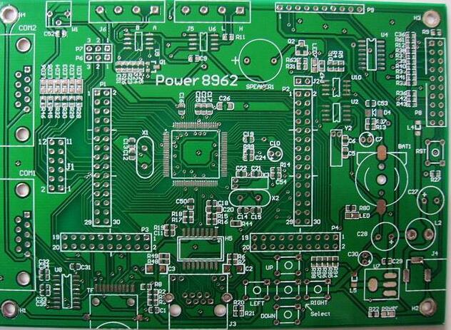
Through hole: It is a common type of through hole. The through hole passes through the entire circuit board and can be used for internal interconnection or as a component installation positioning hole. Through holes are easier to identify. Just pick up the PCB and face the light, and the holes that can see the bright light are through holes.
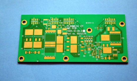
Blind hole: Connect the outermost circuit of the PCB with the adjacent inner layer by plating holes. Because the opposite side cannot be seen, it is called blind pass. It is located on the top and bottom surfaces of the PCB and has a certain depth. It is used to connect the surface line and the underlying inner line. The depth of the hole usually does not exceed a certain ratio (aperture).

Buried via: Refers to the connection of any circuit layer inside the PCB but not conducting to the outer layer. This process cannot be achieved by drilling after bonding. The drilling must be performed on the individual circuit layers. After the inner layer is partially bonded, it must be electroplated before it can be fully bonded. Compared with the original through holes and blind holes It takes more time, so the price is the most expensive. This process is usually only used for high-density circuit boards to increase the usable space of other circuit layers.
Blind vias and buried vias are both located in the inner layer of the circuit board, and are completed by a through-hole forming process before lamination, and several inner layers may be overlapped during the formation of vias.
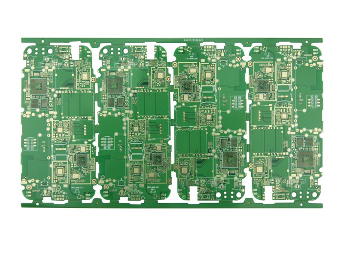
The combination of buried, blind, and through-hole technology is also an important way to increase the density of printed circuits. Generally, the buried and blind holes are all tiny holes. In addition to increasing the number of wiring on the board, the buried and blind holes are interconnected by the "nearest" inner layer, which greatly reduces the number of through holes formed, and the setting of the isolation disk will also be greatly reduced. Reduce, thereby increasing the number of effective wiring and inter-layer interconnection in the board, and improving the high density of interconnection.
Under the same size and number of layers, a multilayer board with a combination of buried, blind, and through holes has an interconnection density that is at least three times higher than that of a conventional full through hole board. That is to say, under the same technical indicators, a circuit board with a combination of buried, blind, and through holes will greatly reduce the size of the board or reduce the number of layers of the board.
Therefore, buried and blind hole technologies have been increasingly used in high-density surface-mounted printed boards. Not only that, but it has been widely used in surface-mounted printed boards in large computers, communication equipment, and civil and industrial applications. It has also been used in some thin boards, such as various PCMCIA, Smard, IC cards and other thin six-layer or more blind-buried multi-layer PCB circuit boards.
The above is an introduction to the types and advantages of vias in PCB. Thank you for reading. I hope this article can help you.