General PCB design drawing inspection items
1) Has the circuit been analyzed? In order to smooth the signal, the circuit is divided into basic units.
2) Does the circuit allow short or isolated key leads?
3) Where must be shielded, is it effectively shielded?
4) Have you made full use of the basic grid graphics?
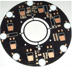
5) Is the size of the printed circuit board the best size?
6) Do you use the selected wire width and spacing as much as possible?
7) Has the preferred pad size and hole size been used?
8) Are the photographic plates and sketches appropriate?
9) Is the use of jumper wires less? Do jumper wires pass through components and accessories?
l0) Are the letters visible after assembly? Are their size and model correct?

11) In order to prevent blistering, is there a window on the large area of copper foil?
12) Are there tool positioning holes?
PCB electrical characteristics inspection items:
1) Have you analyzed the influence of wire resistance, inductance, and capacitance, especially the influence of the critical voltage drop on the ground?
2) Does the spacing and shape of the wire accessories meet the insulation requirements?
3) Has the insulation resistance value been controlled and specified in key areas?
4) Is the polarity fully recognized?
5) Is the influence of wire spacing on leakage resistance and voltage measured from a geometrical point of view?
6) Has the medium for changing the surface coating been identified?
PCB physical characteristics inspection items:
1) Are all pads and their positions suitable for final assembly?
2) Can the assembled printed circuit board meet the shock and vibration conditions?
3) What is the required spacing of standard components?
4) Are the components that are not firmly installed or the heavier parts fixed?
5) Is the heating element heat dissipation and cooling correct? Or is it isolated from the printed circuit board and other heat-sensitive elements?
6) Are the voltage divider and other multi-lead components positioned correctly?
7) Is the arrangement and orientation of the components easy to check?
8) Has it eliminated all possible interference on the printed circuit board and the entire printed circuit board assembly?
9) Is the size of the positioning hole correct?
10) Is the tolerance complete and reasonable?
11) Have you controlled and signed the physical properties of all coatings?
12) Is the diameter ratio of the hole and the lead wire within the acceptable range?
PCB mechanical design factors:
Although the printed circuit board adopts mechanical methods to support the components, it cannot be used as a structural part of the entire device. On the edge of the printing plate, at least every 5 inches for a certain amount of support. The factors that must be considered when selecting and designing printed circuit boards are as follows;
1) The structure of the printed circuit board-size and shape.
2) Types of mechanical accessories and plugs (seats) required.
3) The adaptability of the circuit to other circuits and environmental conditions.