For h igh frequency PCB circuit design, there are currently very good CAD software, its powerful function is enough to overcome the lack of design experience and cumbersome parameter retrieval and calculation, and with powerful network analyzer, it should be a little experience can complete the rf components of good quality. In practice, however, this is not the case.
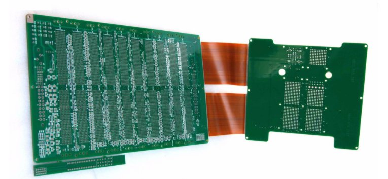
one CAD aided design software and network analyzer
For high frequency circuit design, there are currently very good CAD software, its powerful function is enough to overcome the lack of design experience and cumbersome parameter retrieval and calculation, and with powerful network analyzer, it should be a little experience can complete the rf components of good quality. In practice, however, this is not the case.

CAD design software relies on powerful library functions, including component parameters and basic performance indexes provided by most radio device manufacturers in the world. Many RF engineers mistakenly believe that as long as the tool is used for design, there will be no problem. However, the actual results are always contrary to their wishes. The reason is that they give up the flexible application of the basic concepts of high-frequency circuit design and the accumulation of experience in the application of basic design principles under the wrong understanding. As a result, they often make basic application mistakes in the application of software tools. The CAD software for rf circuit design belongs to transparent visualization software, which uses its various high-frequency basic configuration model libraries to complete the simulation of actual circuit working state. So far, we have understood that the key link of the high-frequency basic configuration model can be divided into two types, one belongs to the centralized parameter form of the component model, the other belongs to the conventional design of the local function model. Therefore, there are the following problems:
(1) Component model and CAD software have developed in a long-term interaction and become increasingly perfect. In practice, we can basically believe in the accuracy of the model. However, the application environment considered by the component model (especially the electrical environment of the component application) are typical values. In most cases, a set of application parameters must be determined empirically, otherwise the actual results are sometimes even farther than the design results without CAD software.
(2) The conventional high-frequency basic configuration model established in CAD software is usually limited to the predictable aspects under the current application conditions, and can only be limited to the basic functional model (otherwise the product research and development does not need human resources, only rely on CAD to do all kinds of products).
(3) It is particularly noteworthy that the establishment of typical function model is completed by applying components in a typical way and constructing in a typical and perfect technological way (including PCB construction), and its performance also reaches a high level of "typical". But in practice, even complete imitation is far from model state. The reason is that although the components and their parameters are the same, their combined electrical environment is not. In low frequency circuits or digital circuits, such a difference of a fraction of a percentage point is not much of a handicap, but in rf circuits, fatal errors often occur.
(4) In the use of CAD software design, software fault-tolerant design does not pay attention to the occurrence of the wrong parameter setting contrary to the actual situation, so, according to the software running path to give an ideal result, but in reality, the result is full of problems. It can be known that the key error lies in not using the basic principles of RF circuit design to correctly apply CAD software.
(5) CAD software belongs to auxiliary tool design, use of the real-time simulation of function, powerful components model library and its typical application function, model base and so on aspects to generate functions to simplify the complex design and calculation of working people, until now, it is far from instead of artificial intelligence in terms of specific design.
The powerful function of CAD software in RF PCB aided design is an important aspect of its popularity. But in practice, many RF engineers are often "backstabbed" by them. Again, the fault tolerance of parameter Settings is the cause. Often use its simulation function to get an ideal model (including various functional links), one to the actual debugging only to find: it is better to use their own experience to design.
Therefore, CAD software in PCB design is still only beneficial to engineers with basic RF design experience and skills, to help them engage in tedious process design (not basic principles design).
Network analyzer is divided into scalar and vector, which is an indispensable instrument for rf circuit design. The general approach is: combined with the basic rf circuit design concept and principles to complete the circuit and PCB design (or use CAD software to complete), according to the requirements of PCB sample processing and assembly prototype, and then use network analyzer for each link of the design of network analysis, it is possible to make the circuit to reach the state. However, the cost of this work is the actual production of at least 3~5 PCB versions, and without basic PCB design p
rinciples and concepts, more PCB versions will be required (or the design will not be completed).
As can be seen from the above:
(1) In the process of using network analyzer to analyze rf circuit, it is necessary to have complete PCB design concept and principle of hf circuit, and it is necessary to be able to clearly know the design defects of PCB through analysis results.
(2) In the process of analyzing the prototype network, we must rely on skilled experimental experience and skills to construct the local functional network. Because in many cases, the circuit defects found by network analyzer can be caused by many factors at the same time, so we must use the construction of local functional network to analyze and thoroughly investigate the cause. This experimental circuit construction must draw on clear high-frequency circuit design experience and proficient circuit PCB construction principles.