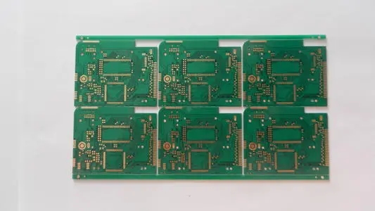
In PCB design.Improving the anti-interference performance of sensitive devices refers to the method of minimizing the pickup of interference noise from the side of sensitive devices and recovering from abnormal conditions as soon as possible.

Common measures to improve the anti-interference performance of sensitive devices are as follows:
(1) Minimize the loop loop area when wiring to reduce induced noise.
(2) When wiring, the power wire and ground wire should be as thick as possible. In addition to reducing the voltage drop, it is more important to reduce the coupling noise.
(3) For the idle I/O ports of the single-chip microcomputer, do not float, but should be grounded or connected to the power supply. The idle terminals of other ICs are grounded or connected to power without changing the system logic.
(4) Use power monitoring and watchdog circuits for the single-chip microcomputer, such as IMP809, IMP706, IMP813, X25043, X25045, etc., which can greatly improve the anti-interference performance of the entire circuit.
(5) On the premise that the speed can meet the requirements, try to reduce the crystal oscillator of the single-chip microcomputer and select low-speed digital circuits.
(6) IC devices should be soldered directly on the circuit board as much as possible, and IC sockets should be used less.
In order to achieve a good anti-interference, we often see the wiring method with ground division on the PCB board. But not all digital circuits and analog circuits must be ground plane split. Because this division is to reduce noise interference.
Theory: The general frequency in digital circuits is higher than that in analog circuits, and their own signals will form a backflow with the ground plane (because in signal transmission, there are various kinds of copper wires and copper wires. Such inductance and distributed capacitance), if we mix the ground wires together, then this backflow will crosstalk each other in the digital and analog circuits. And our separation is to allow them to form a return flow only within ourselves. They are only connected by a zero-ohm resistance or magnetic bead because they are originally the same physical ground. Now the wiring separates them, and finally they should be connected.
How to analyze whether they belong to the digital part or the analog part? This problem is often filtered out when we draw the PCB. My personal opinion is that the key to judging whether a component is analog or digital is to see whether the main chip related to it is digital or analog. For example: the power supply may supply power to the analog circuit, then it is the analog part, if it is supplying power to the single-chip microcomputer or data chip, then it is digital. When they are the same power supply, a bridge method is needed to lead one power supply from another part. The most typical form is D/A. It should be a chip that is half digital and half analog. I think if the digital input can be processed, the rest can be drawn to the analog part.
The analog circuit involves weak and small signals, but the threshold level of the digital circuit is higher, and the requirement for the power supply is lower than that of the analog circuit. In a system with both digital and analog circuits, the noise generated by the digital circuit will affect the analog circuit and make the small signal index of the analog circuit worse. The way to overcome it is to separate the analog ground and the digital ground.
For low-frequency analog circuits, in addition to thickening and shortening the ground wire, the use of one-point grounding for each part of the circuit is the best choice to suppress ground wire interference, mainly to prevent mutual interference between components due to the common impedance of the ground wire.
For high-frequency circuits and digital circuits, since the inductive effect of the ground wire will have a greater impact at this time, one-point grounding will cause the actual ground wire to be lengthened and adversely affected. At this time, a combination of separate grounding and one-point grounding should be adopted.
In addition, for high-frequency PCB, how to suppress high-frequency radiation noise should also be considered. The method is to make the ground wire as thick as possible to reduce the noise-to-ground impedance; full ground, that is, except for the signal transmission printed wire, the other parts are all ground wires . Don't have useless large areas of copper foil.
The ground wire should form a loop to prevent the generation of high-frequency radiation noise, but the area enclosed by the loop should not be too large to avoid induced current when the instrument is in a strong magnetic field. But if it is only a low-frequency circuit, ground loops should be avoided. The digital power supply and the analog power supply should be isolated, and the ground wires should be arranged separately.
There is not much influence in the low frequency, but it is recommended to ground the analog and digital at one point. At high frequencies, the analog and digital grounds can be shared by a magnetic bead.
If the analog ground and the digital ground are directly connected in a large area, it will cause mutual interference. It is neither short-circuit nor proper. There are four ways to solve this problem for the above reasons: 1. Connect with magnetic beads; 2. Connect with capacitor; 3. Connect with inductance; 4. Connect with 0 ohm resistor.
The equivalent circuit of the magnetic bead is equivalent to a band-stop wave limiter, which only has a significant suppression effect on the noise of a certain frequency point. The noise frequency must be estimated in advance in order to select the appropriate model. For situations where the frequency is uncertain or unpredictable, the magnetic beads do not match.