Introduction: Noise and amplifiers are inevitable. Noise reduction is discussed here. The purpose of reducing noise is to reduce it to an acceptable range. It is not and cannot be completely eradicated. In other words, the signal-to-noise ratio can only be as far as possible. Improve, but not infinitely. Below we will first analyze the root cause and mechanism of noise, and then learn about some effective prevention and control measures that have been tested in practice.

Active speakers are a combination of speakers and amplifiers, so the noise analysis of active speakers is similar to that of general amplifiers. HIFI amplifiers can be used for reference in analysis and processing.
It is inevitable that noise is accompanied by amplifiers. The purpose of reducing noise here is to reduce it to an acceptable range, rather than to completely eradicate it. In other words, the signal-to-noise ratio can only be improved as much as possible. But it cannot be infinite. Below we will first analyze the root cause and mechanism of noise, and then learn about some effective prevention and control measures that have been tested in practice.
1. Electromagnetic interference and prevention measures
1) Electromagnetic Interference
The main sources of electromagnetic interference are power transformers and stray electromagnetic waves in space.
Except for a few special products, most active speakers are powered by city electricity, so power transformers must be used. The working process of the power transformer is an "electricity-magnetism-electricity" conversion process, and magnetic leakage will inevitably occur in the electromagnetic conversion process. The transformer leakage is picked up and amplified by the amplifier circuit, and finally appears as a humming sound emitted by the speaker.
The common specifications of power transformers are EI type, ring type and R type. Whether from the perspective of sound quality or electromagnetic leakage, these three types of transformers have their own advantages and disadvantages, and the advantages and disadvantages cannot be simply judged.
EI transformers are the most common and widely used transformers. The major audio production manufacturers in Shenzhen basically use EI transformers. The main sources of magnetic leakage are the air gap between the E and I cores and the coil itself radiation. The magnetic leakage of EI transformer is directional. As shown in the figure below, in the three directions of X, Y, and Z axis, the interference in the Y-axis direction of the coil axis is the strongest, the Z-axis direction is the weakest, and the radiation in the X-axis direction is between Y, Z, so try not to make the Y axis parallel to the circuit board in actual use.
Toroidal transformer
Since the toroidal transformer does not have an air gap and the coil is evenly wound on the iron core, theoretically, there is little magnetic leakage and there is no coil radiation. However, the toroidal transformer has poor anti-saturation ability due to the absence of air gaps, and it is easy to saturate when there is a direct current component in the mains, resulting in strong magnetic leakage. In many areas of the country, the mains waveform distortion is serious, so many users feel that the toroidal transformer is not better than the EI transformer, or even worse. The so-called toroidal transformer has no leakage, either misled by the media, or fabricated by the manufacturer for commercial propaganda. The argument that the magnetic leakage of the toroidal transformer is extremely low is only valid when the mains wave type is a strict sine wave. In addition, the toroidal transformer also has strong electromagnetic leakage at the lead, so the magnetic leakage of the toroidal transformer is also directional. When the toroidal transformer is actually installed, the toroidal transformer is rotated to obtain the highest signal-to-noise ratio at a certain angle.
The R-type transformer can be simply regarded as a toroidal transformer with a circular cross-section, but there are differences in the coil winding method. The heat dissipation condition is far better than that of the toroidal transformer. The iron core is expanded to gradually open and close. The R-type transformer is electromagnetic The leakage situation is similar to the toroidal transformer. Since the length of each turn is shorter than that of the toroidal transformer and can be wound close to the core, the copper loss of the R-type transformer among the above three types of transformers is the smallest.
2. Main prevention and control measures for electromagnetic interference:
1) Reduce the input impedance.
Electromagnetic waves are mainly picked up by wires and PCB traces. Under certain conditions, electromagnetic waves picked up by wires can basically be regarded as constant power. According to the derivation of P=U^U/R, the induced voltage is inversely proportional to the square of the resistance value, that is, the low impedance of the amplifier is very beneficial to reduce electromagnetic interference.
2) Enhance high frequency anti-interference ability
In view of the characteristics that stray electromagnetic waves are mostly medium and high frequency signals, a magnetic sheet capacitor is added to the ground at the input of the amplifier. The capacitance value can be selected between 47-220P. The frequency turning point of the capacitance of hundreds of picofarads is higher than the audio frequency range., Three orders of magnitude, the effect on the sound pressure response and sense of hearing in the effective listening audio segment is negligible.
3) Pay attention to the installation method of power transformer
Use a better quality power transformer, try to extend the distance between the transformer and the PCB board, adjust the position between the transformer and the PCB board, and keep the transformer and the sensitive end away from the amplifier; the EI-type power transformer has different interference strengths in all directions, so pay attention to avoid interference as much as possible The strongest Y-axis direction is aligned with the PCB board.
4) The metal shell must be grounded
For HIFI independent power amplifiers, products with design specifications have an independent grounding point on the chassis. This grounding point actually uses the electromagnetic shielding effect of the chassis to reduce external interference; for common active speakers, it also serves as a radiator. The metal panel also needs to be grounded; the volume and tone potentiometer shells should be grounded as much as possible if conditions permit. Practice has proved that this measure is very effective for PCBs working in harsh electromagnetic environments.
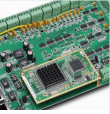
The above is an introduction to the problems and measures in the PCB design of the power amplifier circuit.