1. How to choose the packaging form of resistors and capacitors, and are there any principles? For example, 104 capacitors are available in 0603, 0805 packages, and 10uF capacitors are available in packages such as 3216, 0805, 3528, etc. Which package is more appropriate?

The packaging of resistors and capacitors is related to the specifications of the components. In short, for resistors, packaging is related to resistance (capacitance) and power. The greater the power, the larger the package size; for capacitors, the packaging is related to capacitance and withstand voltage., The higher the capacitance and withstand voltage, the larger the package size. From experience, 0603 package capacitors have a maximum capacitance of 225 (2.2μF), 10μF capacitors, there should be no 0805 package, while 3216, 3528 packages are related to withstand voltage and materials. It is recommended that you refer to the corresponding corresponding components according to the specific components. Datasheet.
2. Sometimes the pins of two chips (such as pin 1 of chip A and pin 2 of chip B) can be directly connected, sometimes between the pins (such as A-1 and B-2). Add a piece of resistor, such as 22 ohms, why is this? What is the function of this resistor? How to choose the resistance value?
Connecting resistors in series between the pin connections of the chip is more common in signal transmission. The function of the resistor is to prevent crosstalk and improve the transmission success rate, and is sometimes used to prevent inrush current. The resistance value is generally small, less than 100 ohms.
3. How to arrange the coupling capacitor? What are the principles? Is a piece of 0.1μF placed on each power pin? Sometimes I see 0.1μF and 10μF used in combination, why?
The coupling capacitor should be as close as possible to the power pin. The coupling capacitor has two functions between the power supply and the ground: on the one hand, it is an energy storage capacitor to avoid voltage drop due to sudden changes in current, which is equivalent to filtering ripple, so it is also called decoupling. On the other hand, the high frequency noise of the device is bypassed, so it is also called bypass. The typical decoupling capacitor value in digital circuits is 0.1μF. The typical value of the distributed inductance of this capacitor is 5μH. The 0.1μF decoupling capacitor has a distributed inductance of 5μH, and its parallel resonance frequency is about 7MHz. That is to say, it has a better decoupling effect for noise below 10MHz, and has little effect on noise above 40MHz. The 0.1μF and 10μF capacitors are used in parallel, and the resonance frequency is above 20MHz. The effect of removing high-frequency noise is better, and the decoupling and bypassing are better considered. In experience, one coupling capacitor should be added for every 10 or so ICs, which can be about 1μF. It is best not to use aluminum electrolytic capacitors. Electrolytic capacitors are rolled up with two layers of film. This rolled up structure behaves as an inductance at high frequencies. Use tantalum capacitors or polycarbonate capacitors. For the selection of decoupling capacitor, press C="1"/F, 10MHz is 0.1μF, 100MHz is 0.01μF.
4. I just learned the design of single-chip microcomputer system. I feel that there are many places where I choose resistors and capacitors based on empirical values. For example, the decoupling capacitor is generally 0.1μF, the pull-up and pull-down resistors are generally 4.7K-10K, and the crystal oscillator start-up circuit capacitance seems to be generally 22pF; also, the package selection of the resistor is based on the power, but how to calculate the specific How much power is needed for the resistor? I think it seems to be experience in many designs. Most of them use 0805 or 0603. The capacitors seem to be similar. It should be no problem if the withstand voltage is slightly larger?
Regarding the choice of capacitance, it is closely related to frequency. Take the matching capacitor of the crystal oscillator as an example. It is mainly used to match the crystal and the oscillator circuit to make the circuit easy to start and be in a reasonable excitation state. It also has a certain "fine-tuning" effect on the frequency. If the frequency is 11.0592MHz, the capacitor is 30pF. ; When the frequency is 22.0184MHz, take 22pF. In addition, the general value of the pull-up resistor is 4.7-10K, and the general value of the pull-down resistor is 10K--100K.
As for the selection of the rated power of the resistor, it is generally 0.25W or 0.125W. At this time, the package is usually 0805 or 0603; but if it is used for current detection or current limiting, it needs to be 0.5W--3W, and the package size must be larger., 3216, 3528 are all possible.
5. What do the so-called 5V TTL devices and 5V CMOS devices mean? Does it mean that the device power supply is connected to 5V, and its pin output or input level is 5V TTL or 5v CMOS?
Broadly speaking, 5V TTL devices and 5V CMOS devices are collectively referred to as 5V devices. It can be said that the device power supply is connected to 5V, and its pin output or input level is 5V TTL or 5V CMOS. However, due to the different materials of TTL and CMOS devices, their driving capability, power consumption, rise time, switching speed and other parameters are very different, and they are suitable for different occasions.
6. The USB socket circuit has a capacitor: 0.01μF/2KV. Is there such a high voltage capacitor? Why do we need to use such a high voltage capacitor here?
0.01μF/2KV, most of them are ceramic capacitors or polypropylene capacitors, which should be safety capacitors, used for power filters, and have EMC and filtering effects. The so-called safety capacitors are used in such occasions: after the capacitor fails, it will not cause electric shock and will not endanger personal safety.
7. What are fan-in, fan-out, fan-in coefficient and fan-out coefficient?
The fan-in coefficient refers to the number of input terminals allowed by the gate circuit. Generally, the fan-in coefficient Nr of the gate circuit is 1--5, and the maximum is not more than 8. If the number of chip input terminals is more than the actual number required, the redundant input terminals of the chip can be connected to high level (+5V) or low level (GND). Fan-out coefficient refers to the number of doors of the same type driven by the output end of a door, or load capacity. Generally, the fan-out coefficient Nc of the gate circuit is 8, and the fan-out coefficient Nc of the driver can reach 25.
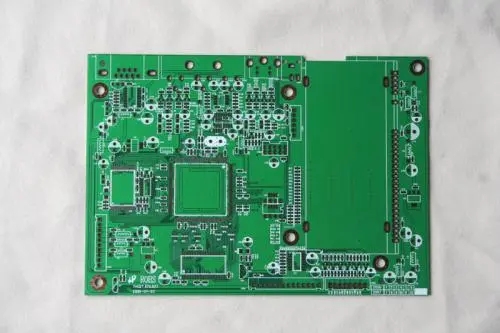
The above is the introduction of 7 common problems in PCB board design. Ipcb is also provided to PCB manufacturers and PCB manufacturing technology.