Whether it is a board made by others or a PCB board designed and manufactured by yourself, the first thing to get it is to check the integrity of the board, such as tinning, cracks, short circuits, open circuits, and drilling. If the board is more rigorous, Then you can check the resistance between the power supply and the ground wire by the way.
Under normal circumstances, the self-made board will install the components after the tinning is completed, and if people do it, it is just an empty tinned PCB board with holes. You need to install the components yourself when you get it. .
Some people have a lot of information about the PCB boards they design, so they like to test all the components at one time. In fact, it is recommended to do it bit by bit.
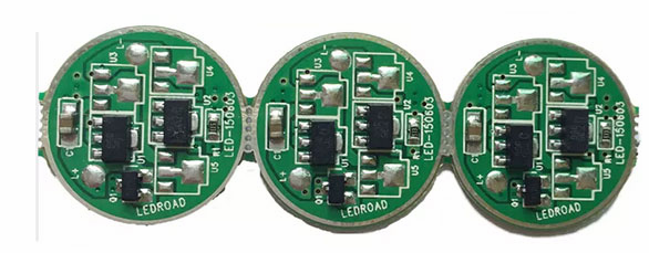
PCB circuit board under debugging
New PCB board debugging can start from the power supply part. The safe method is to put on a fuse and connect the power supply (just in case, use a stabilized power supply).

Use a stabilized power supply to set the overcurrent protection current, and then slowly increase the voltage of the stabilized power supply. This process requires monitoring the input current, input voltage and output voltage of the board.
When the voltage is adjusted upwards, there is no over-current protection and the output voltage is normal, then it means that the power supply part of the board has no problem. If the normal output voltage or over-current protection is exceeded, then the cause of the fault must be investigated.
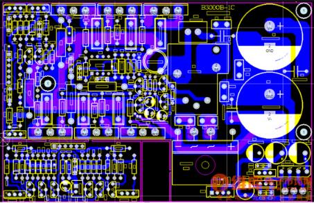
Circuit board component installation
Gradually install the modules during the debugging process. When each module or several modules are installed, follow the above steps to test, which helps to avoid some more hidden errors at the beginning of the design, or installation errors of components, which may lead to overcurrent burns. Bad components.
If a failure occurs during the installation process, the following methods are generally used to troubleshoot:
Troubleshooting method one: voltage measurement method
Measuring voltage method
When over-current protection occurs, do not rush to disassemble the components, first confirm the power supply pin voltage of each chip to see if it is in the normal range. Then check the reference voltage, working voltage, etc. in turn.
For example, when the silicon transistor is turned on, the voltage of the BE junction will be around 0.7V, and the CE junction will generally be 0.3V or less.
When the BE junction voltage is found to be higher than 0.7V during the test (special transistors such as Darlington are excluded), then it is possible that the BE junction is open. Sequentially, check the voltage at each point to eliminate the fault.
Troubleshooting method two: signal injection method
Signal injection
The signal injection method is more troublesome than measuring the voltage. When the signal source is sent to the input terminal, we need to measure the waveform of each point in turn to find the fault point in the waveform.
Of course, you can also use tweezers to detect the input terminal. The method is to touch the input terminal with tweezers, and then observe the response of the input terminal. Generally, this method is used in the case of audio and video amplifier circuits (note: hot floor circuit and high voltage circuit) Do not use this method, it is prone to electric shock accidents).
This method detects that the previous stage is normal and the next stage responds, so the fault is not on the next stage, but on the previous stage.
Troubleshooting method three: other
PCB circuit board appearance inspection machine
The above two are relatively simple and direct methods. In addition, for example, seeing, smelling, listening, touching, etc., which are often said, it is an engineer who needs some experience to be able to detect the problem.
Generally, "look" is not to see the state of the testing equipment, but to see whether the appearance of the components is complete; "smell" mainly refers to whether the smell of the components is abnormal, such as the smell of burnt, electrolyte, etc. The general components are When damaged, it will give off an unpleasant burning smell.
And "listening" is mainly to listen to whether the sound of the board is normal under working conditions; about "touching", it is not to touch whether the components are loose, but to feel whether the temperature of the components is normal by hand, for example, it should be cold under working conditions. The components are hot, but the hot components are abnormally cold. Don't pinch it with your hands directly during the touching process to prevent the hand from being burned by the high temperature.