Selection and method of high-precision PCB wiring
Printed circuit boards {Printed circuit boards}, also known as printed circuit boards, are providers of electrical connections for electronic components.
Printed circuit boards are often represented by "PCB", but cannot be called "PCB boards".
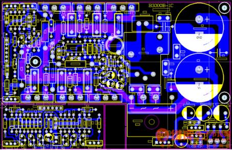
When making high-precision PCB circuit boards, the choice of circuit corner wiring form is to make the circuit board easy to manufacture and beautiful. The design needs to set the circuit corner mode, which can choose 45°, 90° and arc. Generally, sharp corners are not used, and it is best to use circular arc or 45° to prevent 90° or sharper corner transitions.
The connection between the wire and the pad should also be as smooth as possible to avoid small sharp feet, which can be solved by repairing the copper mold. When the pad core distance is lower than the outer diameter of the pad, the wire spacing can be the same as the pad diameter; if the pad core distance exceeds, the wire spacing should not exceed the pad diameter. When wires pass between two pads without connecting to them, keep the maximum and equal distance from them. Similarly, the distance between the wire and the wire should be uniform, equal and maximum.

How to determine the width of the wire of a high-precision PCB circuit board: The width of the wire depends on the current level of the wire and anti-interference factors. The greater the current, the wider the wire should be. Generally speaking, the power line should be wider than the signal line. In order to ensure the stability of the ground potential (less affected by changes in the ground current), the ground wire should be wider. Experiments show that when the copper film thickness of the printed wire is 0.05mm, the current-carrying capacity of the printed wire can be calculated at 20A/mm2, that is, a 0.05mm thick and 1mm wide wire can pass 1A current. Therefore, for general signal lines, a distance of 10-30 mils can meet the requirements; for high-voltage, high-current signal lines, the distance is greater than or equal to 40 mils, and the line distance exceeds 30 mils. In order to ensure the anti-stripping strength and working reliability of the wire, the widest wire should be used as much as possible, and the circuit impedance should be reduced within the allowable range of high-precision PCB area and density, and the anti-interference performance should be improved.
iPCB is a high-tech manufacturing enterprise focusing on the development and production of high-precision PCBs. iPCB is happy to be your business partner. Our business goal is to become the most professional prototyping PCB manufacturer in the world. Mainly focus on microwave high frequency PCB, high frequency mixed pressure, ultra-high multi-layer IC testing, from 1+ to 6+ HDI, Anylayer HDI, IC Substrate, IC test board, rigid flexible PCB, ordinary multi-layer FR4 PCB, etc. Products are widely used in industry 4.0, communications, industrial control, digital, power, computers, automobiles, medical, aerospace, instrumentation, Internet of Things and other fields.