There is a saying in copper casting PCB design, "Copper is free." This means that the PCB editor designer must think the other way around. The circuit board starts with pure copper, and the unnecessary copper is removed. Compared with most bare circuit boards of the same size, circuit boards that are mainly made of copper can be built faster, consume less, and cost less. Choosing the right technology will make a difference between a relaxing or frustrating experience.
There are two most common ways to maximize copper behavior:
Manual-This method is usually faster, but sloppy. By defining and placing specific shapes, copper can be quickly placed as objects. You can assign these routing objects to the network and check for short circuits or errors during the continuity check. This technique is suitable for fast turns or prototype construction.
Automatic-This method is more time consuming; however, copper pouring can better promote the maximum use of copper. Instead of laying out the circuit board and then returning and placing a copper shape to fill it, you can leave the largest amount of copper by drawing a border around the circuit board area and pouring the copper in.
How to save time with copper pouring
When the copper is poured, the boundary is defined, and when the pouring operation is performed, everything in it will be automatically connected and executed. If the area is large, the shape is unusual, or a few irregularly shaped objects are filled, this technique is usually easier and faster. The pouring operation will automatically fill in multiple irregular areas. In addition, it will automatically isolate other parts or traces in the area.

Objects on the same network (such as ground plane) will be connected according to the settings page or design rules. The objects that can be processed automatically by copper casting are vias, traces, nets, decals, void areas and pads. When used correctly, the copper pouring will automatically connect to avoid unnecessary connections. These connections can be double checked using a continuity check tool.
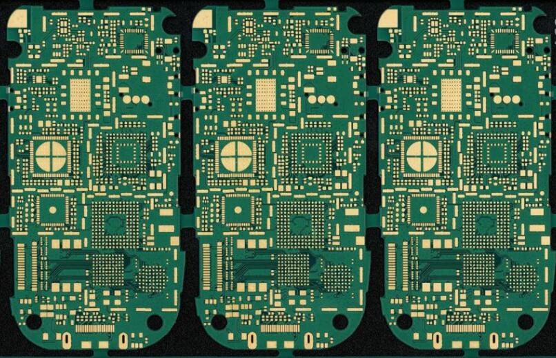
Image source: Flickr User Low Voltage Laboratory (CC BY 2.0)
When to use manual or automatic methods for PCB design
Many times we tend to operate manually because it seems to be a faster solution in the short term, and we don't need to give up control of our design. However, when you look at the big picture, the automated method may be a better long-term option, even if it is more upfront work. The use of copper casting in the following three situations may be a better choice for your design.
Polygon management
Manual-If you are making a prototype, please don't waste your time making the design look beautiful, especially if the design warrants changes. Creating a traditional closed shape of copper is quick and easy, but when you are dealing with unusual polygons, it can be time consuming. A quick and dirty technique is to place overlapping squares, triangles and trapezoids next to each other and on top of each other to build your shape. While this is useful for short-term solutions, you will eventually need to do some vertex editing to clean up your design, which can be tedious.
Automatic-The use of copper pouring in this process is automatic because it can prevent you from fully managing the polygons. By defining a border and pouring in copper wire, you can avoid creating objects that need to be adjusted when changes are made later.
Manual-PCB Factory In the printed circuit board PCB design, the plane is a large area of copper, and all connections are a net. If you are building a circuit board with a separate plane and frequently adding and replacing parts, you can achieve a simpler short-term solution through point-to-point wiring.
Automatic-If your design uses ground planes, this is a good way to avoid several traces all reaching the same point. Copper pouring is particularly effective. Defining and pouring the copper plane will automatically connect all connections on a network.
Thermal management
Manual-A quick way to cool hot parts is to add a large copper square to the decal to help dissipate heat. This may work best if you have enough space to use, but in many cases this is not the case.
Automatic-You can define the area around the most important parts and give them priority. Even the stitched via matrix can be easily filled with water on both sides. Use it when the most important thing is to maximize the copper surface area.
When using copper casting, the time it takes to define connection rules will enable future designs to be perfectly poured, allowing you to focus on functionality rather than connectivity. This investment will save time for future designs.
Smart copper editors can organize these differences in a simple and meaningful way to automatically apply general, marginal and specific requirements when pouring copper. Smart copper editing can also help manage other areas, such as board edges and unique areas. In the PCB layout design rules, specific rules specific to copper casting are used to define vias, traces, nets, decals, void areas and pads.