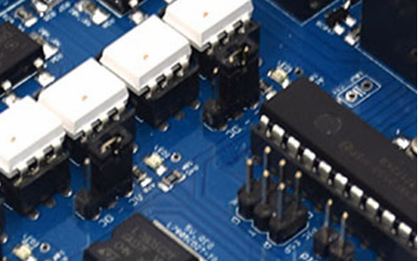
In the process of PCB copying, especially when copying some high-precision circuit boards, testing is an indispensable step, and only testing can evaluate whether these PCB copy boards are qualified. As everyone knows, the most commonly used testing equipment in circuit board copying is the flying probe tester and test rack testing. In fact, there is another electronic tester called AOI. AOI is a new type of test technology that has only emerged in recent years, but it has developed rapidly. At present, many manufacturers have introduced AOI test equipment. During automatic inspection, the machine automatically scans the PCB board through the camera, collects images, compares the tested solder joints with the qualified parameters in the database, after image processing, checks out the defects on the PCB copy board, and uses the display or automatic marking to identify the defects Display/mark it out for repair by technicians.
1. Implementation objectives: The implementation of AOI has the following two main objectives:
(1) End quality. Monitor the final state of the product when it leaves the production line. When the production problem is very clear, the product mix is high, quantity and speed are the key factors, this goal is preferred. AOI is usually placed at the end of the production line. In this position, the equipment can generate a wide range of process control information.
(2) Process tracking. Use inspection equipment to monitor the production process. It typically includes detailed defect classification and component placement offset information. When product reliability is important, low-mix high-volume manufacturing, and stable component supply, manufacturers prioritize this goal. This often requires the inspection equipment to be placed in several locations on the production line, to monitor the specific production conditions in real time, and to provide the necessary basis for the adjustment of the production process.
Placement location Although AOI can be used in multiple locations on the production line, and each location can detect special defects, the AOI inspection equipment should be placed in a location that can identify and correct the most defects as soon as possible.

2. There are three main inspection positions:
(1) After solder paste printing. If the solder paste printing process meets the requirements, the number of defects found by ICT can be greatly reduced. Typical printing defects include the following: A. Insufficient solder on the pad. B. Too much solder on the pad. C. Poor registration of the solder to the pad. D. Solder bridge between pads.
In ICT, the probability of defects relative to these situations is directly proportional to the severity of the situation. Slightly small amounts of tin rarely cause defects, while severe cases, such as no tin at all, almost always cause defects in ICT. Insufficient solder may be a cause of missing components or open solder joints. Nevertheless, deciding where to place the AOI needs to recognize that component loss may occur under other reasons, and these reasons must be included in the inspection plan. Inspection of this location most directly supports process tracking and characterization. The quantitative process control data at this stage includes printing offset and solder volume information, and qualitative information about printed solder is also generated.
(2) Before reflow soldering. The inspection is done after the components are placed in the solder paste on the board and before the PCB circuit board is sent into the reflow oven. This is a typical location for inspection machines, because most defects from solder paste printing and machine placement can be found here. The quantitative process control information generated at this location provides information on the calibration of high-speed chip machines and fine-pitch component placement equipment. This information can be used to modify component placement or to indicate that the placement machine needs to be calibrated. The inspection at this location satisfies the goal of process tracking.
(3) After reflow soldering. The inspection is performed at the last step of the SMT process. This is currently the most popular choice for AOI, because all assembly errors can be found at this location. Post-reflow inspection provides a high degree of security because it identifies errors caused by solder paste printing, component placement, and reflow processes.