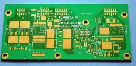
PCBA lecture hall: possible causes of the BGA pillow effect (head-in-pillow)
Head-in-Pillow (HIP) refers to the undesirable phenomenon of solder joints, which is named after the shape of a person's head resting on a pillow.
The pillow effect (Head-in-Pillow, HIP) is mainly used to describe the BGA parts of the circuit board. Warpage or deformation caused by other causes separates the solder ball of the BGA from the solder paste printed on the PCB circuit board. When the circuit board passes through the high-temperature reflow zone, the temperature gradually drops and cools. At this time, the IC carrier board and The deformation of the circuit board also slowly returns to the state before the deformation (sometimes it will not go back), but the temperature at this time is already lower than the melting temperature of the solder ball and solder paste, that is to say, the solder ball and solder paste It has already condensed from the molten state back to the solid state. When the warpage of the BGA carrier board and the circuit board slowly returns to the shape before the deformation, the solder ball and solder paste that have become solid will come into contact with each other again, thus forming something like a head resting on a pillow Welding shape of false welding or false welding.
HIP (Head-In-Pillow) detection
According to the above theory, most of the pillow effect (HIP) should occur on the edges of the BGA parts, especially the corners, because the warpage is the most serious there. If this is the case, you can try to use a microscope or optical fiber internal viewing Observe through a mirror, but usually only the two outermost rows of solder balls can be seen in this way, and it is difficult to identify them further inside. Moreover, to observe the BGA solder balls in this way, you must ensure that there are no high parts next to them to block the line of sight. Now the circuit board The high-density design is quite restrictive in implementation.

In addition, the pillow effect (HIP) is generally difficult to find from the current 2D X-Ray inspection machine, because most of the X-Ray can only be inspected from top to bottom, and the position of the broken head cannot be seen. If there is, it can be rotated up and down. The angle of X-Ray should be able to be observed. Sometimes it can be detected by in-board test (ICT, In Circuit Test) and function test (FVT, Function Verification Test), because this type of machine usually uses a needle bed operation method, which requires additional external pressure on the circuit board., So that the solder balls and solder paste that were next to each other have a chance to separate, but there will still be many defective products flowing into the market, usually such defective products will be quickly found by customers to have functional problems and be returned Therefore, how to prevent the pillow effect is actually an important issue for SMT.
In addition, you can also consider burning the board (Burn/In) to filter out the boards with HIP (if the veneer is burned to increase the temperature), because the temperature of the board will increase during the burning, and the temperature will The board is deformed, the board is deformed, and the solder joints of empty/fake soldering have a chance to appear. Therefore, the program must be added for self-diagnosis test when burning the machine. If the location of the HIP is not on the circuit of the program test, it cannot be found. NS.
At present, the more reliable methods to analyze the adverse phenomena of HIP are Red Dye Penetration and Cross Section, but both of these methods are destructive tests, so it is not recommended to use them unless necessary.
Recently, the technology of [3D X-Ray CT] has made a breakthrough, which can effectively check the shortcomings of this type of HIP or NWO (Non-Wet-Open) welding, and it has gradually become popular, but the cost of the machine is still not enough. Just cheap.
Possible causes of HIP
Although the pillow effect occurs during reflow soldering, the actual cause of the pillow effect can be traced back to poor materials, and at the circuit board assembly plant side, it can be traced back to the printing of solder paste, the placement of parts/slices. The accuracy and the temperature setting of the reflow furnace...etc.
Below are several possible reasons for the disadvantages of pillow effect (HIP):
1. BGA package (Package)
If there are solder balls of different sizes in the same BGA package, the smaller solder balls are prone to the disadvantage of the pillow effect.
In addition, when the temperature resistance of the carrier board of the BGA package is insufficient, the carrier board may be warped and deformed during reflow soldering, thereby forming a pillow effect.
(warpage of substrate, inconsistent bump size)
HIP-Ball sizes vary
2. Solder paste printing
The amount of solder paste printed on the solder pad is different, or there are so-called via-in-pads on the circuit board, which will cause the possibility that the solder paste cannot touch the solder balls. And form a pillow effect.
In addition, if the solder paste printing deviates too far from the solder pads of the circuit board, this usually occurs when multiple boards are assembled. When the solder paste melts, it will not provide enough solder to form a bridge, which will have a chance to cause a pillow effect.
(insufficient solder paste volume, printing misalignment)
HIP-Solder Paste Printing Uneven HIP-Solder Paste Printing Offset
3. Insufficient precision of placement machine (Pick&Place)
If the precision of the placement machine is insufficient or the XY position and angle are not adjusted properly when placing the parts, the problem of the misalignment of the BGA solder balls and the solder pads will also occur.
In addition, the placement machine will slightly depress the Z-axis distance when placing IC parts on the circuit board to ensure that the BGA solder balls are in effective contact with the solder paste on the circuit board pads, so that BGA soldering can be ensured during reflow soldering. The balls are perfectly soldered to the pads of the circuit board. If the force or formation of the Z-axis downward pressure is insufficient, there is a chance that some solder balls will not be able to contact the solder paste, which will cause the chance of HIP.
(Inaccurate XY placement, insufficient placement force)
HIP-parts are placed offset HIP-parts under pressure
4. Reflow profile
When the reflow temperature or the heating rate is not set properly, problems such as no tin melting or circuit board and BGA carrier board bending or board warping will easily occur, which will form HIP. You can refer to the article on possible causes of simultaneous BGA soldering and short circuit to understand the BGA soldering caused by the BGA carrier board and the circuit board due to the large difference in CTE and the too long TAL (Time Above Liquids). And short-circuit analysis.
In addition, it should be noted that if the temperature of the preheating zone rises too fast, it will easily drive the flux to volatilize prematurely, which will easily form solder oxidation and cause poor wetting. Secondly, it is better not to adjust the peak temperature too high or too long. It is recommended to refer to the temperature and time recommendations of the parts.
HIP-part warping
5. Solder ball oxidation
After the BGA is completed in the PCB factory, the probe will be used to contact the solder balls for functional testing. If the cleanliness of the probe is not treated well, there is a chance that contaminants will be contaminated on the BGA solder balls and lead to poor soldering. Secondly, if the BGA package is not properly stored in a temperature and humidity controlled environment, there is a good chance that the solder balls will be oxidized to affect the bonding properties of the solder.