"Ground" is a very important concept in electronic technology. In the PCB design process, we will encounter various grounds, such as digital ground, analog ground, and signal ground. In this article, we might as well understand the various "grounds" in the switching power supply.
The concept of "land"
The classic definition of "ground" is "the equipotential point or plane used as a reference for a circuit or system."
The symbol of "earth"
Ideally, the ground wire should be a physical entity with zero potential and zero impedance. In the actual wiring, on the PCB ground wire, which has impedance components, and reactance components composed of distributed capacitance and inductance. In addition, the ground wire and the source (power source, signal source) form a loop. The electric field of this loop will induce the RF current of the external electromagnetic field, which is often referred to as "noise", which will cause EMI problems.
Consideration of "ground" in the actual wiring process of switching power supply
【General Provisions】
.According to the actual application, first distinguish the types of ground wires, and then choose different grounding methods.

.Regardless of the grounding method, the principle of "low impedance, low noise" must be observed.
Classification of "ground" in switching power supply
1. DC ground
DC circuit "ground", zero potential reference point.
2. Exchange place
The neutral line of alternating current, this kind of ground is usually the ground that produces noise, and should be distinguished from the earth.
3. Analog ground
The zero potential of various analog signals.
4. Digital ground:
Also called logical ground, it is the zero potential of various switching (digital) signals of digital circuits.
5. Hot ground
The switching power supply does not need to use a power frequency transformer, and the "ground" of its switching circuit is related to the mains power grid, the so-called "hot ground", which is live.
6. Cold:
Because the high-frequency transformer of the switching power supply isolates the input and output ends; and because the feedback circuit often uses a photocoupler, it can not only transmit the feedback signal, but also isolate the "ground" of both sides; so the ground at the output end is called "cold ground", It is not live.
7. Power ground
Zero potential reference point for high current network devices, power electronics and magnetic devices.
8. Signal ground
Generally refers to the ground wire of the sensing change signal.
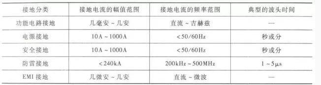
9. Safely
Provide a return to the ground point to prevent the risk of electric shock.
10. Shield ground
Provide 0V reference or electromagnetic shielding for interconnecting cables and main racks to prevent electrostatic induction and magnetic field induction.
11. Systematic
The common reference point for analog and digital signals of the entire system.
12. Floating ground
Use a branch in the circuit as a 0V reference without grounding.
The way of grounding
1. Single point grounding
.It means that the ground wires of all circuits are connected to the same point of the common ground wire to reduce the mutual interference between the ground loops.
.It can prevent the current and RF current in different subsystems from passing through the same return path, thereby avoiding mutual common mode noise coupling.
.According to the characteristics of different systems, you can choose series single-point grounding and parallel single-point grounding.
2. Multi-point grounding
Refers to the nearby grounding of each part of the circuit in the system.
3. Mixed grounding
.Combine the comprehensive application of single-point grounding and multi-point grounding. Generally, it is grounded at multiple points through some inductors or capacitors on the basis of single-point grounding. It uses the characteristics of inductance and capacitors that have different impedances at different frequencies The ground wire system has different grounding structures at different frequencies, which is mainly suitable for circuit systems working at mixed frequencies.
.Pay attention to distinguish the ground of the analog circuit and the ground of the digital circuit, and their best common connection point.
Reminder: In the low-frequency circuit, the working frequency of the signal is less than 1MHz, the inductance between the PCB wiring and the device has little influence, and the circulating current formed by the grounding circuit has a greater influence on the interference, so single-point grounding should be adopted. When the signal operating frequency is greater than 10MHz, the ground wire impedance becomes very large. At this time, the ground wire impedance should be reduced as much as possible, and the nearest multiple points should be used for grounding. When the operating frequency is between 1 and 10 MHz, if single-point grounding is used, the length of the ground wire must not exceed 1/20 of the wavelength, otherwise, multi-point grounding should be used.