Whether military or civil aircraft,there will be several sets of communication equipment.Some with satellite,some with ground. Whatever the connection,Microwave High-Frequency PCB aircraft hf antenna is needed. Even a small quadrotor drone, also through the GPS antenna to locate.

Similarly, more and more arrays of antennas are available in smart cars,such as various cellular bands,Wi-Fi,even 5G and its MIMO requirements,V2V (vehicle-to-vehicle),radar (77GHz, etc.), etc. Their own mobility makes the design more difficult. The antenna design and layout of autonomous vehicles will become more like aircraft design in terms of RF requirements and constraints.
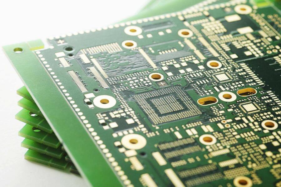
High-frequency PCB (HF)
High frequency (HF) communication systems provide voice communication over long distances. It provides communication between aircraft or ground station and aircraft.
The HF system operates at frequencies between 2MHz and 29.999MHz. The system uses the Earth's surface and the ionosphere to bounce communication signals back and forth. The distance reflected varies with time, radio frequency, and the altitude of the aircraft hf antenna.
The control panel sends the selected frequency information and control signal to the transceiver. The audio control panel sends these signals to the REU:
- RF PCB radio selection signal
- Receive volume control
- Press call (PTT)
During transmission, microphone audio and PTT signals enter the HF transceiver via the REU.A transceiver uses a microphone to modulate the RF carrier signal generated by the transceiver. The transceiver sends the modulated RF signal to the antenna via the antenna coupler for transmission to other aircraft or ground stations.
Also during launch,the flight data acquisition component receives PTT signals from the transceiver.DFDAU uses PTT as a keying signal to record emission events.
During receiving,the antenna receives the modulated RF signal and sends it to the transceiver via the antenna coupler. The transceiver demodulates or separates the audio from the RF carrier. The received audio is sent from the HF transceiver via the REU to the in-flight intercom speaker and headset.
Select Call Decoder to receive audio from HF Transceiver. The SELCAL decoder monitors the audio of SELCAL calls from ground stations.
HF transceivers receive discrete air/ground signals. The HF transceiver uses this discrete signal to calculate the flight segment for the internal fault memory.
The HF antenna is at the leading edge of the vertical stabilizer.
The antenna coupler is inside the vertical stabilizer.
Warning: When launching the HF system, ensure personnel are at least six feet (2 meters) away from the vertical stabilizer. Radiating RF energy from an HF antenna is harmful to humans.

VHF communication system
The VHF communication system provides sound and data line-of-sight communication for the unit. The VHF communication system can be used to communicate between aircraft and between aircraft and ground stations.
The radio tuning frequency range for VHF communications is 118.00 to 136.975MHz. VHF radios are used by transmitters to receive voice communications.
The operating frequency of VHF communication system is 118.00MHz to 136.975MHz. The 8.33 kHz interval is applicable only in these frequency bands:
- 118.000-121.400
- 121.600-123.050
- 123.150-136.475
Instrument Landing System (ILS)
Course track antenna
The course-track antenna has two elements. One component provides an RF input to the ILS receiver 1, and the other component provides an RF input to the ILS receiver 2. The course track antennas receive frequencies from 108.1MHz to 111.95MHz, with odd bits spaced at one-tenth of the bandwidth.
Glide path antenna
The glide path antenna also has two elements. One element provides an RF signal input to MMR 1, and the other element provides an RF signal input to MMR 2. The glide path antenna receives frequencies from 328.6 MHz to 335.4 MHz.
The glide path and course path antennas are located in the front radome. The glide path antenna is above the weather radar antenna. The course track antenna is below the weather microwave radar antenna.

Pointing beacon system
The beacon system provides audio and video instructions as the aircraft crosses the airport runway over the beacon transmitter.

Radio altimeter system
A radio altimeter (RA) system measures the vertical distance from the aircraft to the ground. The radio altitude is displayed on the display unit (DU) in the cockpit. The radio altitude is calculated using the receiver transmitter assembly to compare the transmitted and received signals. The R/T module transmits a radio signal and then receives a reflected RF signal from the ground to determine the altitude of the aircraft. The R/T outputs the calculated altitude data to the two ARINC 429 data buses and to the systems used on the aircraft.
Flight crews and other aircraft systems use altitude data during low altitude flight, approach and landing. The range of the system is 20 to 2500 feet.
The adjustablemicrowave radio minimum altitude warning is operated by the radio altitude system and can be independently selected from 0 to 999 feet by the captain and first officer on the EFIS control panel. This radio minimum height option is compared and processed in the Display Electronics Unit (DEU) with the pre-existing radio height values from the radio height receiver/transmitter output. When the aircraft descends to the selected radio minimum altitude, a blinking radio minimum warning appears on the available DU.
The RA antenna is at the bottom of the body.

Traffic warning and collision avoidance system
The Traffic Alert and Collision Avoidance System (TCAS) helps the crew maintain a safe distance between air traffic and other aircraft equipped with ATC transponders. TCAS is an airborne system that operates independently of the ATC system on the ground. TCAS sends interrogations to nearby aircraft that are equipped with ATCRBS transponders or a type of air traffic control S-mode transponder in response to the interrogations.TCAS uses these transponders to calculate the distance between them, the relative azimuthm, and the altitude of the responding aircraft. If the responding aircraft does not report an altitude, the TCAS cannot calculate the altitude of that aircraft. The aircraft being tracked by the TCAS is called the target. Using information from the transponder and the altitude of its own aircraft, the TCAS calculates the relative motion between the target and its own aircraft. The TCAS then calculates how close the target will get to its aircraft at the closest approach point (CPA).
The target is classified as one of four, depending on the interval at the CPA point and the time at which the CPA point will occur:
-- Other traffic
-- Proximity to traffic
- the invaders
- a threat.
Various objects have different symbols on the display.

VOR is system
The VOR system has two VHF omnidirectional beacon/pointing beacon (VOR/MB) receivers. The receiver has VOR and pointing functions. This section covers only VOR work for VOR/MB receivers.
The navigation (NAV) control panel provides manually tuned input to the VOR/MB receiver. There are two navigation control panels, one for the captain and the other for the co-pilot. The RF signal from the VOR/LOC antenna passes through the power distributor and then reaches the VOR/MB receiver. VOR/MB receivers use RF signals to calculate ground station direction and decode Morse code station identifier signals and station audio signals.
The receiver transmits VOR direction to the remote magnetic indicator (RMI). RMI azimuth pointer selector can be used to select the RMI azimuth pointer from the display VOR or ADF ground station azimuth.

Air traffic control system
The air traffic control (ATC) ground station questions the airborne ATC system, and the ATC transponder answers its questions to the ground station in a coded message in the desired format.
ATC transponders also respond to S-mode queries from the Traffic Avoidance System (TCAS) of other aircraft or ground stations.
When a TCAS computer on a ground station or another aircraft interrogates this ATC system, the transponder emits a pulse-code response signal from which the aircraft and its altitude can be identified and indicated.
The ATC antenna is located at the front of the fuselage near the centerline. The top antenna is located at 430.25. The bottom antenna is located at station 355.

rangefinder
The range finder (DME) system provides oblique (line-of-sight) distance measurements between the aircraft and the ground station.
The DME system has two interrogators and two antennas.
The interrogator receives both manually tuned input and automatically tuned input from the Flight Management Computer System (FMCS) on the navigation control panel. If the navigation control panel tuning input fails, the interrogator receives the auto-tuning input directly from the FMC.
The DME system sends data to the display electronic assembly for display on the main flight display (PFD) and navigation display (ND).

Automatic directional machine system
Automatic Directing Machine (ADF) system is a navigation aid system. The ADF receiver uses the amplitude modulation (AM) signal from the ground station to calculate the position of the ADF ground station relative to the longitudinal axis of the aircraft. The ADF system also receives standard AM radio broadcasts.
The ADF antenna is located on the upper fuselage at fuselage station 694. iPCB is a High-Tech Manufacturing Enterprises focusing on the development and production of high precision PCB.