High-frequency PCB design engineers generally select high-frequency PCB materials from the following aspects.
1. Low dielectric constant
2. Low loss factor
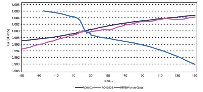
3. Stable frequency
4. Stable inflation and contraction
5. PCB cost (material cost, design-test-manufacturing cost)
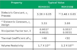
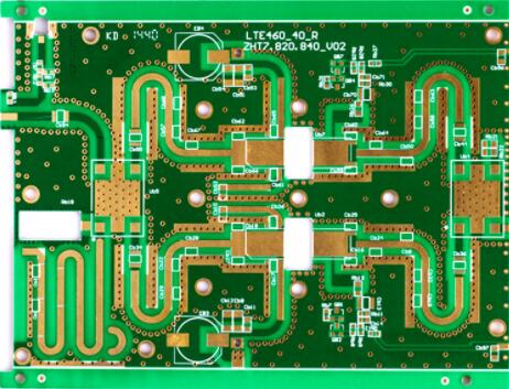
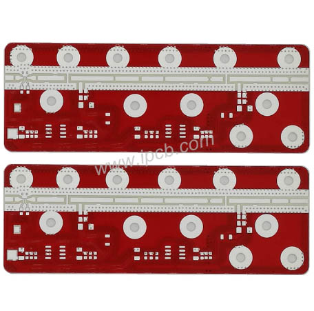
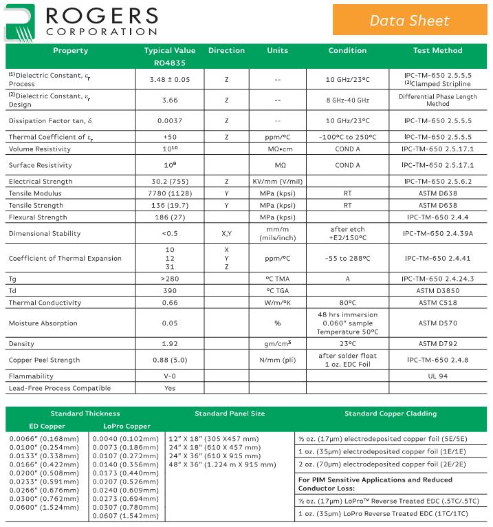
RO4350B produced by Rogers is a low-loss material of hydrocarbon resin and ceramic filler laminate and semi-cured sheet, which has excellent high-frequency performance (generally can be applied below 30GHz). Because RO4350B is processed with standard epoxy resin/glass (FR-4) processing technology, it also has low line processing cost. It can be said that RO4350B achieves the optimization of cost and high-frequency performance, and is the most cost-effective low-loss high-frequency material. In order to better meet the design requirements, we tested the insertion loss of the microstrip transmission line based on RO4350B material at 24 GHz when designing the microstrip array antenna.
Analysis of insertion loss of microstrip line
The insertion loss of microstrip line mainly includes conductor loss, dielectric loss, surface wave loss and radiation loss, of which conductor loss and dielectric loss are the main ones. The skin effect makes the high frequency current on the microstrip line concentrate on the thin layer of the conductive band and the ground plate directly contacting the dielectric substrate, and the equivalent AC resistance is much greater than the low frequency case. When the operating frequency is below 10GHz, the conductor loss of the microstrip line is much greater than the dielectric loss. When the operating frequency rises to 24GHz, the dielectric loss exceeds the conductor loss.

HFSS Calculation Results of Microstrip Line Insertion Loss
For the insertion loss of microstrip lines with different lengths calculated by HFSS, the dielectric substrate is RO4350B with a thickness of 20 mil. It can be seen from the above figure that the insertion loss of the microstrip line is about 17dB/m, in which the metal loss, dielectric loss and other losses are 4.47dB/m, 11.27dB/m and 1.26dB/m respectively. For comparison, Table 1 shows the insertion loss of the microstrip line calculated by MWI2016. It can be seen that the calculated value of MWI is 24.4dB under the same conditions, in which the dielectric loss value is close, but the conductor loss value is 7dB. The reason for the difference is that the surface roughness of the guide band and ground plate is not considered in the HFSS model.
Measures to reduce insertion loss of microstrip line
1. Reasonable selection of plate thickness and reduction of welding resistance layer
For microstrip lines with the same characteristic impedance, the conductor loss decreases with the increase of the dielectric thickness, while the dielectric loss is basically unchanged. The reason is that the thicker the dielectric substrate, the narrower the microstrip line width, the more concentrated the high-frequency current, and the greater the conductor loss. It is worth noting that the larger loss tangent angle of the solder mask medium at 24GHz will increase the insertion loss of the microstrip line. Therefore, when designing a 24GHz microstrip antenna, the antenna area needs to be soldered and windowed.
2. LoPro copper foil is preferred
The surface roughness of copper foil of guide strip and ground plate is also an important factor affecting the insertion loss of microstrip line. The smoother the copper foil surface, the smaller the conductor loss. RO4350B provides electrolytic copper foil (ED) and low roughness reverse processing copper foil (LoPro). The surface roughness of ED copper foil is about 3um, and the LoPro copper foil can reach 0.4um, so it can effectively reduce conductor loss. Compared with the insertion loss of the two copper foils, the dielectric substrate thickness is 0.1mm. At 24 GHz, the insertion loss of LoPro copper foil microstrip line is 40% less than that of ED copper foil.

Comparison of insertion loss between electrolytic copper and reverse copper
3. Reasonable selection of surface treatment process
Surface treatment process is also one of the factors affecting conductor loss. There are four common surface treatment processes, including silver precipitation, gold precipitation (nickel gold), nickel gold precipitation (nickel 3-5 um, gold 2.54-7.62 um) and tin precipitation. Table 2 shows the electrical parameters of these metals, of which nickel is a ferromagnetic material with a magnetic permittivity of 600. According to the calculation formula of skin depth, the skin depth of nickel is one order of magnitude smaller than that of other metals, so the surface resistance of nickel is dozens of times larger than that of other metals, resulting in the conductor loss of nickel gold process is much larger than that of other processes. The thickness of the substrate is 20 mil due to the insertion loss of bare copper, silver precipitation and nickel gold surface treatment processes. It can be seen from the figure that the insertion loss of the silver deposition process is similar to that of bare copper, but the insertion loss of microstrip line after nickel gold surface treatment is 4 dB/m (10 GHz) larger, which can be predicted to be greater at 24 GHz.

Comparison of insertion loss between nickel gold process and bare copper
When we use RO4350B dielectric substrate to design 24GHz microstrip antenna or microstrip circuit, we need to comprehensively consider the dielectric plate thickness, copper coating type and surface treatment process according to the performance and cost requirements. The conclusion is also applicable to most materials of Rogers RO4000 and RO3000 series.